

Image signal processing apparatus and a control method thereof, and an image pickup apparatus and a control method thereof
- Summary
- Abstract
- Description
- Claims
- Application Information
AI Technical Summary
Benefits of technology
Problems solved by technology
Method used
Image

Examples
embodiment 1
[0039]This embodiment will describe a configuration in which reduces display delay by connecting an YCC signal extracted from a portion of a signal processing circuit for recorded image to a processing circuit for displayed image, with an example being a video camera.
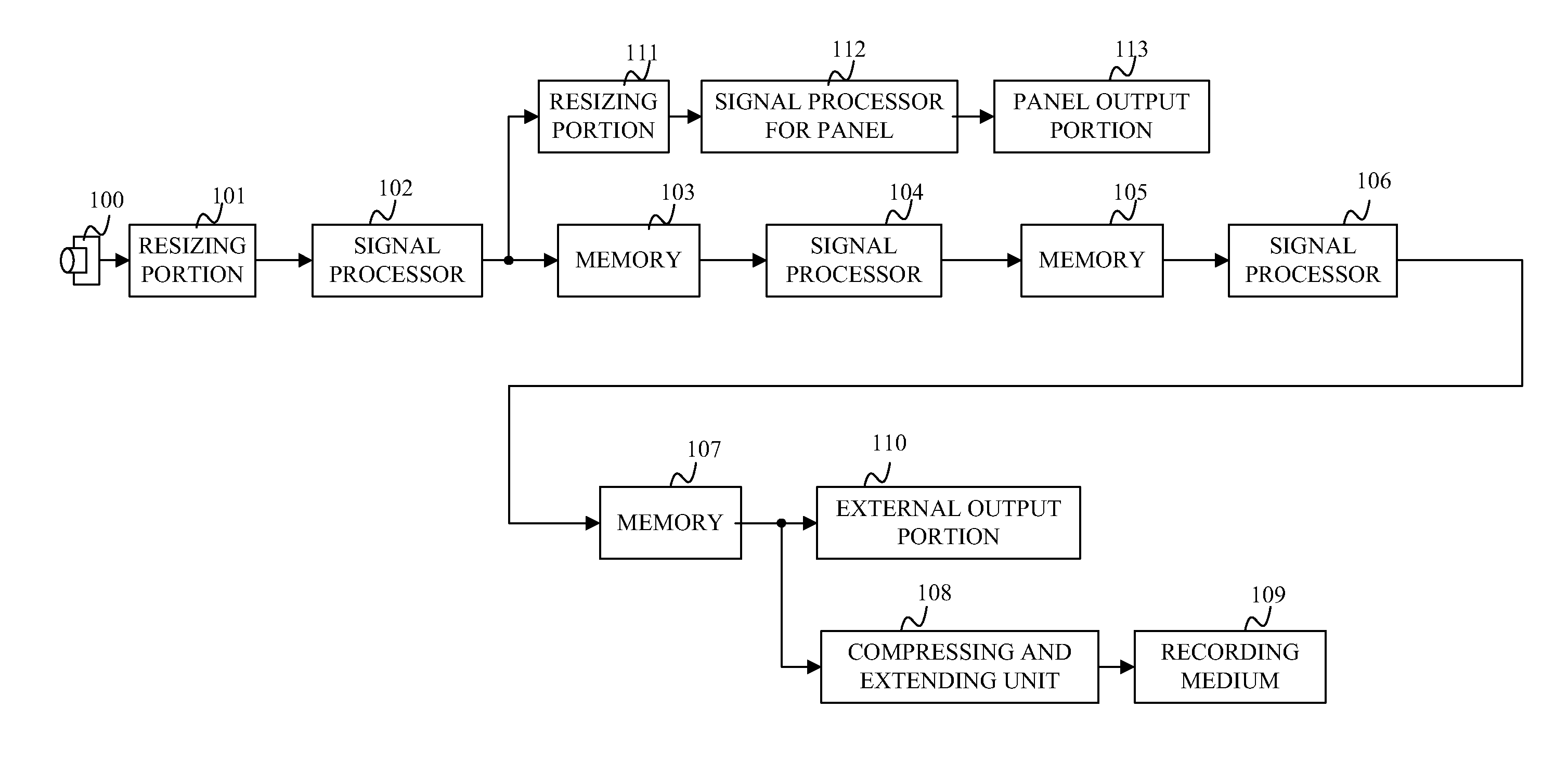
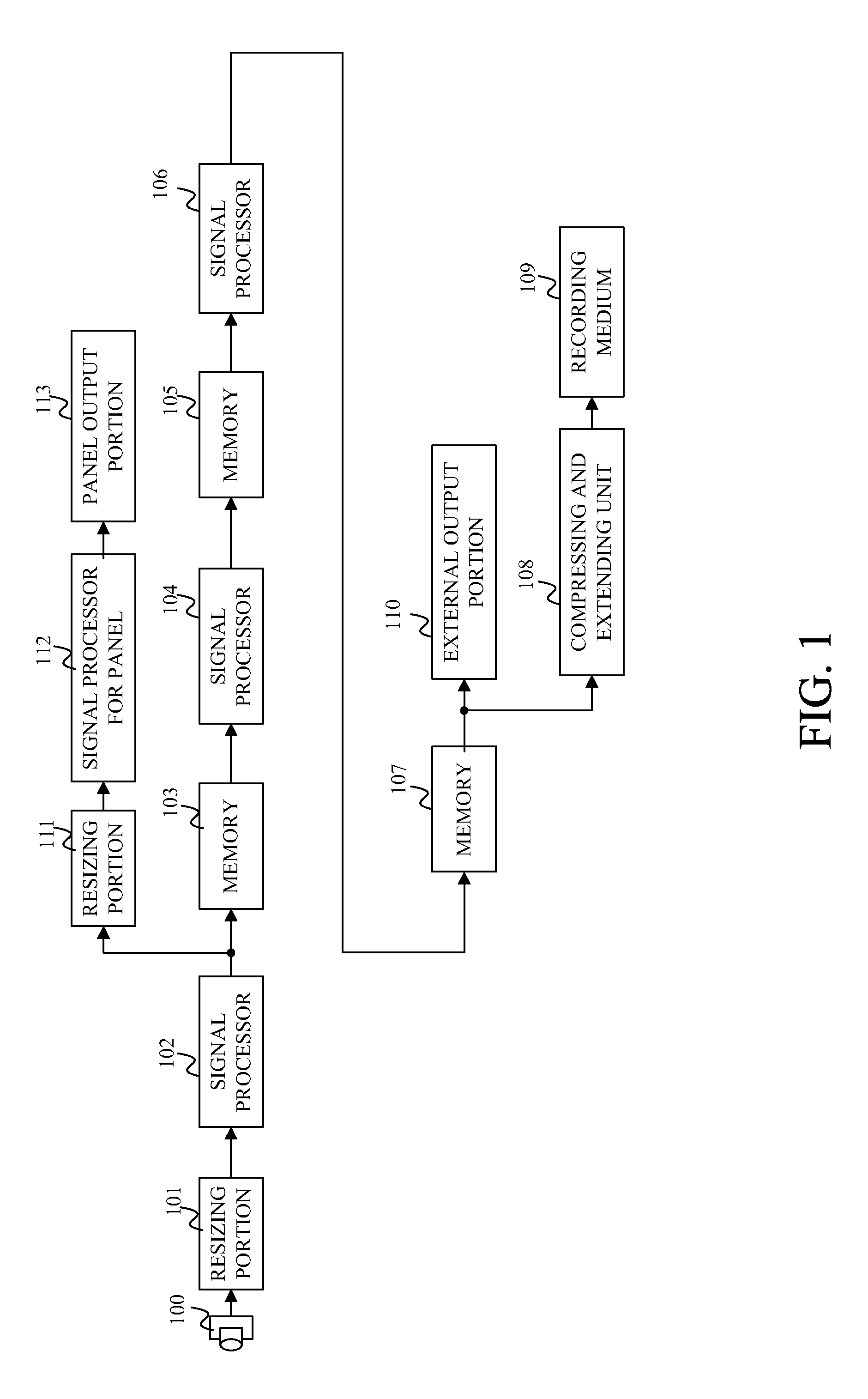
[0040]First, a description will be given of the function configuration of this embodiment with reference to the function configuration block diagram of FIG. 1.
[0041]A sensor 100 is an image pickup element such as a CCD or CMOS sensor. The sensor 100 adjusts an incident light intensity and a focus state with a group of objective lenses (not illustrated in the figure), photoelectrically converts a formed image, and then outputs the image as a digitalized signal. The image pickup element has, at its each pixel, a color filter of R (red), G (green), or B (blue) which is arranged in a predetermined array, e.g., a bayer or honeycomb array, and used to produce an R, G, or B image signal, respectively. For high speed output, an...
embodiment 2
[0072]This embodiment will describe a configuration in which reduces display delay by connecting an RGB image signal extracted from a portion of the signal processing circuit for recorded image to the processing circuit for displayed image, with an example being a video camera.
[0073]First, a description will be given of the function configuration of this embodiment with reference to the function configuration block diagram of FIG. 3. A description will be given only of a portion which is different from the configuration of Embodiment 1, and will be omitted for the same portion as the configuration of Embodiment 1 to which the same reference numerals as those of Embodiment 1 are given.
[0074]A resizing portion 114 reduces the size of the RGB image output by the resizing portion 101 to the display size on the panel. When the size of the RGB image is reduced, an image band is controlled by a band limiting filter in both horizontal and vertical directions relative to the RGB image to pre...
embodiment 3
[0098]This embodiment will describe a configuration in which a display delay is reduced by connecting an YCC signal extracted from a portion of the signal processing circuit for recorded image to the processing circuit for displayed image, with an example being a video camera. In this embodiment, the frame rate during driving of the sensor 100 is different from the frame rate during output on the panel.
[0099]First, a description will be given of the function configuration of this embodiment with reference to the function configuration block diagram of FIG. 5. A description will be given only of a portion which is different from the configurations of Embodiments 1 and 2, and will be omitted for the same portion as the configurations of Embodiments 1 and 2 to which the same reference numerals as those of Embodiments 1 and 2 are given.
[0100]A memory 117 is a block necessary for conversion of a frame rate. The memory 117 operates at the same frame rate as that of the driving cycle of th...
PUM
 Abstract
Description
Claims
Application Information