

Apparatus for Manipulating a Wind Turbine Blade and Method of Blade Handling
a technology for manipulating apparatus and wind turbine blades, applied in the direction of propellers, propulsive elements, water-acting propulsive elements, etc., can solve the problems of slings exerting potentially damaging forces on blade parts, relative sliding, and increasing repair or replacement problems,
- Summary
- Abstract
- Description
- Claims
- Application Information
AI Technical Summary
Benefits of technology
Problems solved by technology
Method used
Image

Examples
first embodiment
[0055]As best seen in FIGS. 11 to 13 the blade manipulating apparatus in accordance with the invention is shown in complete operative form. The apparatus, indicted 30, comprises three primary structural components, including blade connection structures in the form of blade brackets 32 which make connection to the blade, support frames 34 to which the brackets 32 are connected, and a turner base structure 36 on which the support frames sit and by which the fames and blade carried thereby can be rotated about a generally horizontal axis.
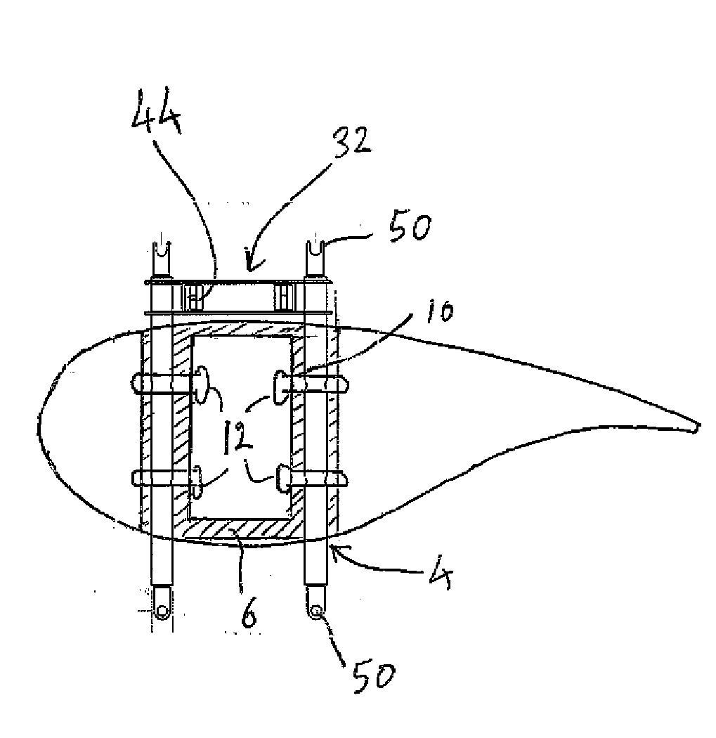
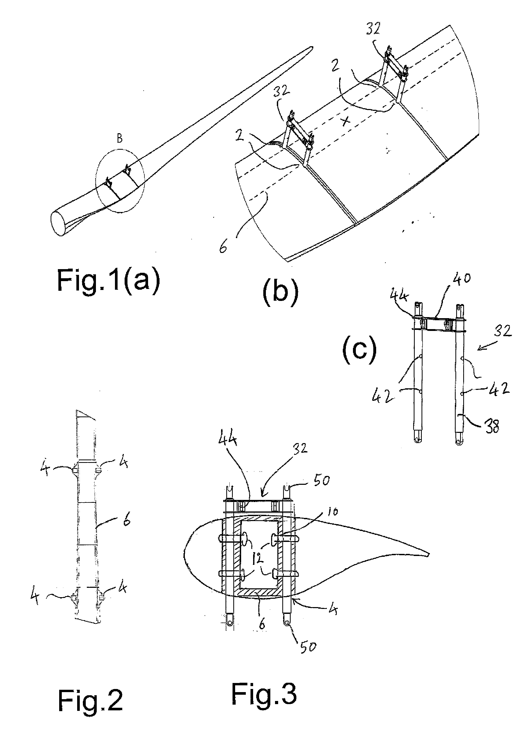
[0056]Returning to FIG. 1(c), this shows a blade bracket 32. This comprises a pair of depending legs or pins 38 for receipt in the shear tubes 4 of the blade lifting points interconnected by a crosspiece 40. The legs 38 are formed with the openings 42 through which the shear pins 12 are passed to lock the bracket to the blade. Lifting eyes 44 most clearly seen in FIG. 9 are formed on the bracket 32, conveniently on the crosspiece 40, these serving as a...
second embodiment
[0064]Although the aforedescribed embodiment makes connection to a blade in which lifting points are arranged in pairs, with suitable adaptation to blade and apparatus instead of a pair of lifting points spaced across the blade chord at a given blade radius, a single lifting point may be provided. FIGS. 14 to ??? illustrate an apparatus for blade manipulation for making connection to a single lifting point.
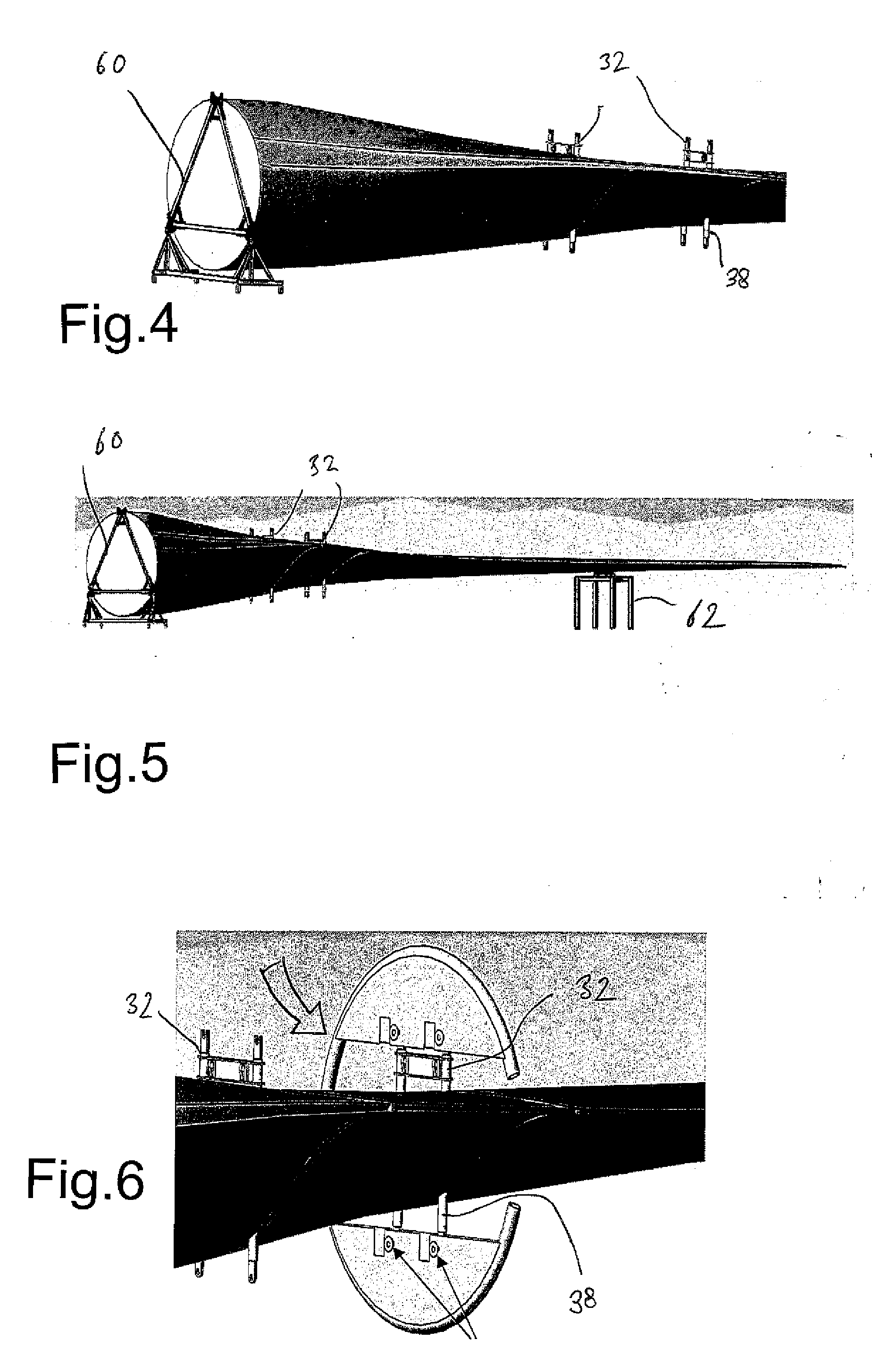
[0065]FIGS. 14 to 19 illustrate a second embodiment of an apparatus for blade manipulation. The apparatus takes the form of a mobile unit 60 having a turner base 62 here provided with wheels whereby it may be driven around the factory or blade storage park. The turner base 62 carries a pair of spaced generally curved frames 64, interconnected by a cross member 66. More particularly, the frames 64 each comprise a main part-circular portion 68 and extending from an end of the part-circular portion 68, an inwardly extending support portion 70 to which the cross member 66 is connected...
fourth embodiment
[0071]FIG. 23 illustrates a blade manipulating apparatus according to the invention. A turner base structure 100 is shown having an enlarged lower region and an upstanding portion 101 of part-circular outer form from which extends a pivotably mounted support structure 102. The support structure 102 is mounted to extend from a shaft 104 to allow its rotation about a generally horizontal axis. The support structure 102 carries two pairs of blade connecting structures 106 in the form of connecting pins, upstanding from the support structure 102 of which one pair is visible, for engagement in the blade lifting points in the manner as described above. Note that the pins may or may not extend through the complete thickness of the blade. The support structure 102 is driven to move on its shaft 104 through the action of a drive motor and gear connection (not illustrated) arranged between the base 100 and shaft or support structure 102. The apparatus allows movement of the blade between a le...
PUM
 Abstract
Description
Claims
Application Information