Full cell system and method of humidifying and cooling the same

Inactive Publication Date: 2014-07-10
HYUNDAI MOTOR CO LTD
View PDF3 Cites 7 Cited by
  • Summary
  • Abstract
  • Description
  • Claims
  • Application Information

AI Technical Summary

Benefits of technology

[0016]The present invention has been made in an effort to provide a fuel cell system having advantages of cooling compressed air in which a temperature has risen under high power oper

Problems solved by technology

Additionally, an outlet temperature of the air compressor 132 rises to about 120° C. and thus it is disadvantageous to operate the humidifier 136 and the stack 110 at this time.
However, because t

Method used


Image

  • Full cell system and method of humidifying and cooling the same
  • Full cell system and method of humidifying and cooling the same
  • Full cell system and method of humidifying and cooling the same

Examples


Example

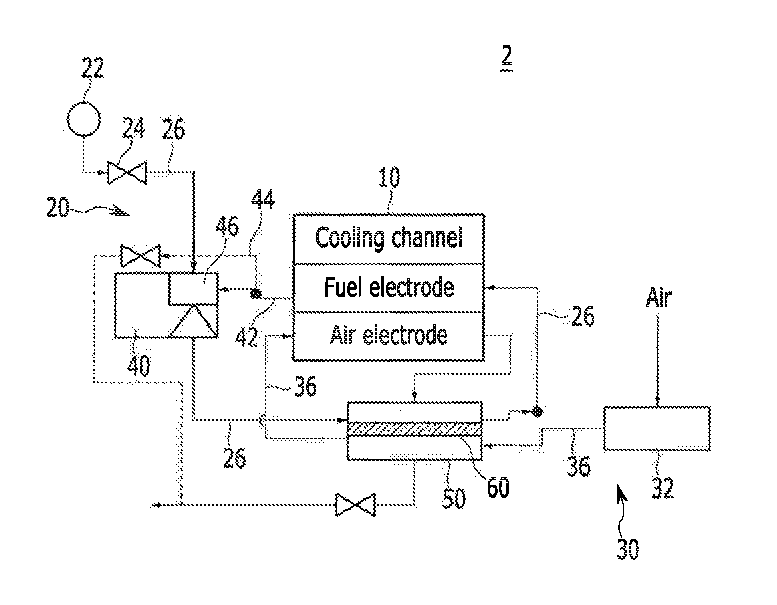
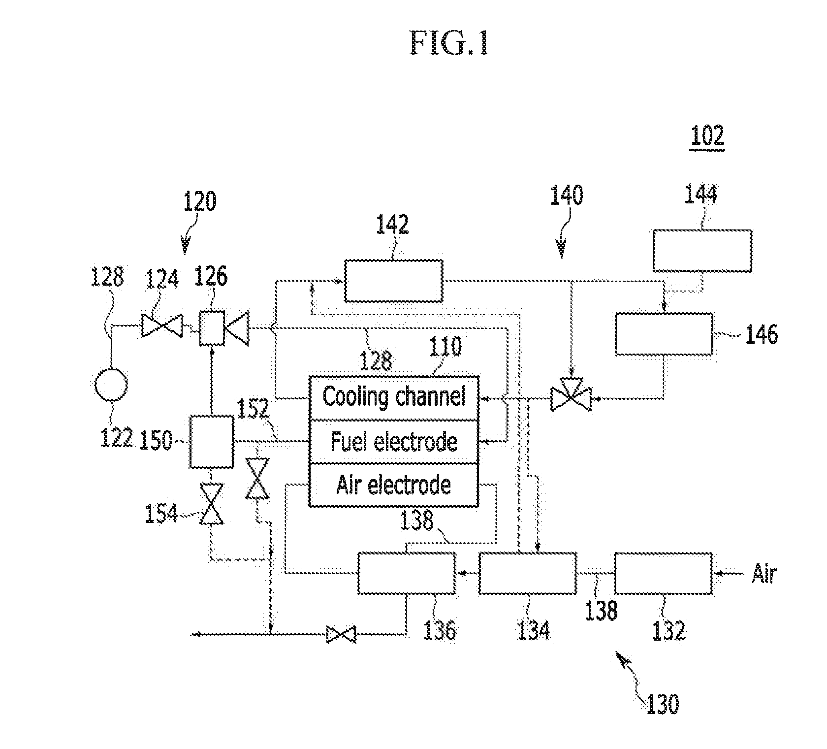
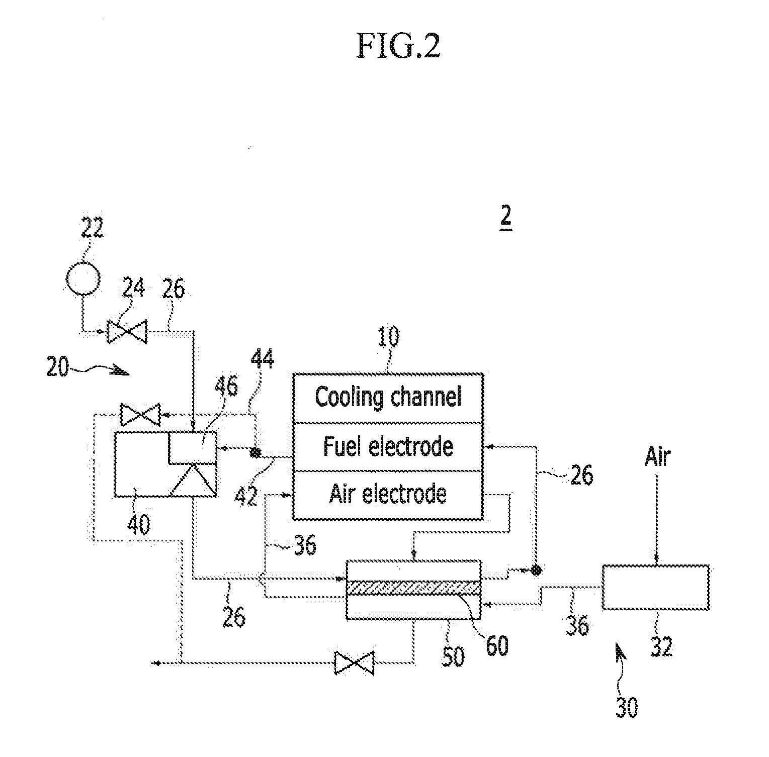
[0034]The present invention will be described more fully hereinafter with reference to the accompanying drawings.

[0035]Although exemplary embodiments of the present invention have been shown and described, it will be apparent to those having ordinary skill in the art that a number of changes, modifications, or alterations to the invention as described herein may be made, none of which depart from the spirit of the present invention.

[0036]It is understood that the term “vehicle” or “vehicular” or other similar term as used herein is inclusive of motor vehicles in general such as passenger automobiles including sports utility vehicles (SUV), buses, trucks, various commercial vehicles, watercraft including a variety of boats and ships, aircraft, and the like, and includes hybrid fuel cell vehicles, electric fuel cell vehicles, plug-in hybrid fuel cell vehicles, a hydrogen-powered fuel cell vehicles, etc. As referred to herein, a hybrid vehicle is a vehicle that has two or more sources ...


PUM


Abstract

A method of humidifying and cooling a fuel cell system is provided. The method of humidifying and cooling a fuel cell system includes: exhausting, by a fuel supply unit, a hydrogen gas to a reservoir in which condensed water of an anode is stored. Additionally, a hydrogen gas and condensed water are pumped and the hydrogen gas and the condensed water are exhausted to the humidifier. Additionally, compressed air of an air compressor is delivered to the humidifier heat is exchanged with compressed air in the humidifier. The hydrogen gas and compressed air in which a heat is exchanged in a humidified state is delivered to an anode and a cathode, respectively.

Description

CROSS-REFERENCE TO RELATED APPLICATION[0001]This application claims priority to and the benefit of Korean Patent Application No. 10-2012-0158605 filed in the Korean Intellectual Property Office on Dec. 31, 2012, the entire contents of which are incorporated herein by reference.BACKGROUND OF THE INVENTION[0002](a) Field of the Invention[0003]The present invention relates to a fuel cell system and a method of humidifying and cooling the same that efficiently humidify a fuel cell and cools compressed air using condensed water of the anode.[0004](b) Description of the Related Art[0005]Typically, as shown in FIG. 1, a fuel cell system 102 includes a stack 110 that generates electrical energy through an electrochemical reaction, a fuel supply unit 120 that supplies a hydrogen gas, which is fuel to the stack 110, an air supply unit 130 that supplies air necessary for the electrochemical reaction to the stack 110, and a heat / water management unit 140 that removes a reaction heat of the stac...

Claims


Application Information

Patent Timeline
IPC IPC(8): H01M8/04
CPCH01M8/04067H01M8/04141H01M8/04014H01M8/04097Y02E60/50F24F6/00B01D63/02B01D69/08H01M8/04149
Inventor NOH, YONG GYUKWON, HYUCK ROULSHIM, HYO SUB
Owner HYUNDAI MOTOR CO LTD
Why Eureka
Try Eureka