Tracheal Intubation Device

a tracheal intubation and tube technology, applied in the field of medical devices, can solve the problem that the endotracheal tube cannot be precisely placed into the trachea of a patient by medical personnel

Inactive Publication Date: 2014-07-10
CHEN TIEN SHENG
View PDF3 Cites 23 Cited by
  • Summary
  • Abstract
  • Description
  • Claims
  • Application Information

AI Technical Summary

Benefits of technology

[0011]According to another embodiment of the present invention, the bar-shaped camera is made of a rigid material that allows the bar-shaped camera to guide the direction of movement of the endotracheal tube while the endotracheal tube is moving.

Problems solved by technology

Consequently, since the glottis of the trachea cannot be observed, the endotracheal tube cannot be precisely placed into the trachea of a patient by medical personnel.

Method used


Image

  • Tracheal Intubation Device
  • Tracheal Intubation Device
  • Tracheal Intubation Device

Examples


first embodiment

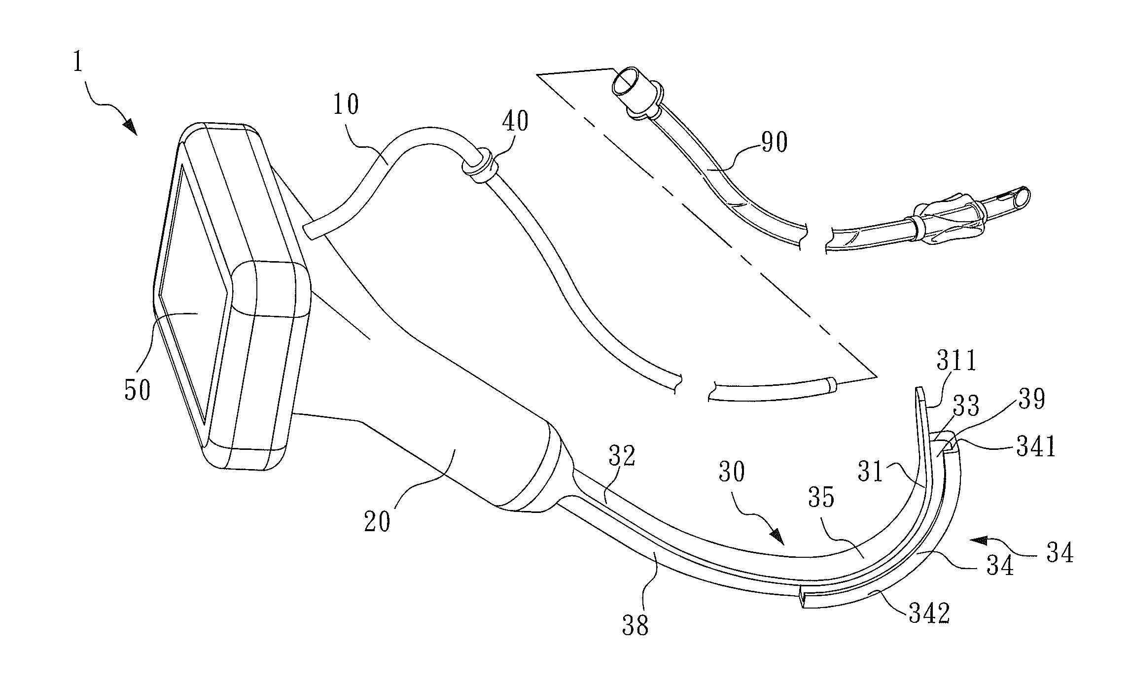
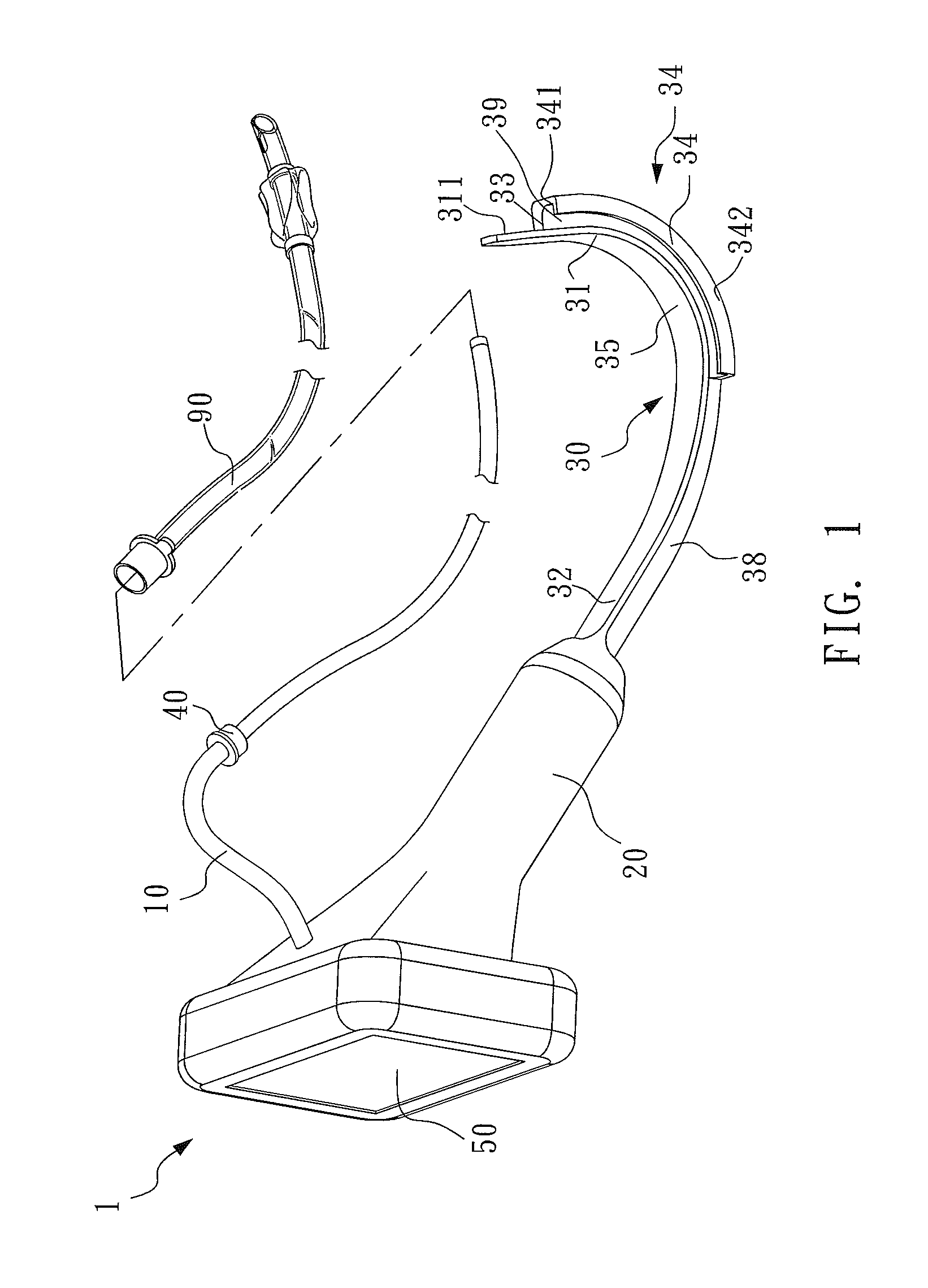
[0026]As shown in FIG. 1, the guiding portion 30 is connected to the handle portion 20, and the guiding portion 30 comprises a front end 31, a rear end 32, a tongue piece 35, a barrier 33 and a slot portion 34. The rear end 32 of the guiding portion 30 is connected to the handle portion 20. The slot portion 34 is situated at the front end 31 of the guiding portion 30. The tongue piece 35 is extended form the rear end 32 to the front end 31. The barrier 33 is extended form the rear end 32 to the front end 31 and substantially perpendicular to the tongue piece 35. The slot portion 34 comprises a main surface portion 341 which is connected with the barrier 33 and substantially paralleled to the tongue piece 35. The slot portion 34 is connected with the front end 31, thus a restricted passage 39 is formed by the tongue piece 35, the slot portion 34 and the barrier 33. An open passage 38 is formed by the tongue piece 35 and the barrier 33; therefore, the endotracheal tube 90 and the bar-...

third embodiment

[0031]Please refer to FIG. 5, FIG. 5 is an exploded view illustrating the tracheal intubation device of the present invention and the endotracheal tube.

[0032]The difference between the tracheal intubation device 1a of the third embodiment and the tracheal intubation device 1 is that there is no the surface portion 341 or restricted part 342 disposed the guiding portion 30a. The tracheal intubation device 1a only has a tongue piece 35 and a barrier 33. The tongue piece 35 is substantially perpendicular to the barrier 33. The bar-shaped camera 10a of the tracheal intubation device 1a in this embodiment is detachably connected to the handle portion 20, and the bar-shaped camera 10a is made of a rigid material that is curved to guide the direction of movement of the endotracheal tube 90 while it is moving. The bar-shaped camera 10 and the endotracheal tube 90 in this embodiment are accommodated within an area formed by the tongue piece 35 and the barrier 33, and the endotracheal tube 90...

fifth embodiment

[0036]As shown in FIG. 8, according to the present invention, the tracheal intubation device ld of the present invention comprises the bar-shaped camera 10a, the handle portion 20a, the guiding portion 30b, and the display device 50. The bar-shaped camera 10a is placed inside the endotracheal tube 90 to ensure that the endotracheal tube 90 can be precisely placed into the glottis of the trachea by reference to the image captured by the bar-shaped camera 10. The handle portion 20a has two convex points 21 individually disposed at the lateral insides of the handle portion 20a for detachably connected with the guiding portion 30b.

[0037]As shown in FIG. 8, the guiding portion 30b is detachably connected to the handle portion 20a, and the guiding portion 30b comprises a front end 31, a rear end 32, a tongue piece 35, a barrier 33a and a slot portion 34a. The rear end 32 comprises a connection portion 321 for detachably connecting with the handle portion 20a. The slot portion 34a is situ...


PUM


Abstract

A tracheal intubation device for placing an endotracheal tube in the trachea of a patient includes a bar-shaped camera, a handle portion, a guiding portion, and a display device. The bar-shaped camera for capturing images is placed inside the endotracheal tube. The display device is electrically connected to the bar-shaped camera for displaying images captured by the bar-shaped camera. The guiding portion connected to the handle portion has a front end and a rear end. The rear end is connected to the handle portion, and the bar-shaped camera and the endotracheal tube are movably situated in the guiding portion.

Description

CROSS REFERENCE[0001]The present application is a continuation of U.S. application Ser. No. 13 / 354,388 filed on Jan. 20, 2012.BACKGROUND OF THE INVENTION[0002]1. Field of the Invention[0003]The present invention relates to a medical device. More specifically, the present invention relates to a tracheal intubation device for placing an endotracheal tube into the trachea of a patient.[0004]2. Description of the Related Art[0005]For apnea patients, tracheal intubation is an essential operation for sustaining respiration to maintain the vital signs of a patient. Medical personnel have to place an endotracheal tube into the trachea of a patient to ensure that oxygen is provided in a short period of time. Therefore, it is an important task for medical personnel to place the endotracheal tube efficiently. In practice, tracheal intubation devices equipped with a camera are often used by medical personnel to confirm the location of the trachea of a patient and then to place the endotracheal ...

Claims


Application Information

Patent Timeline
Patent Type & Authority Applications(United States)
IPC IPC(8): A61B1/05A61B1/00A61M16/04A61B1/267
CPCA61B1/053A61B1/267A61B1/00052A61M16/0488A61B1/00004A61B1/0002A61B1/00016A61B1/00066A61B1/00048A61M2205/502A61B1/00105A61B1/00108
Inventor CHEN, TIEN-SHENG
Owner CHEN TIEN SHENG
Why Eureka
Try Eureka