

Clamp for automatic welding
An automatic welding and fixture technology, which is applied in welding equipment, auxiliary welding equipment, welding/cutting auxiliary equipment, etc., can solve the problems of low production efficiency, inability to unify positions, and high labor intensity of workers, so as to improve welding accuracy and quality, Improve production efficiency, accurate and convenient operation
- Summary
- Abstract
- Description
- Claims
- Application Information
AI Technical Summary
Problems solved by technology
Method used
Image

Examples
Embodiment 1
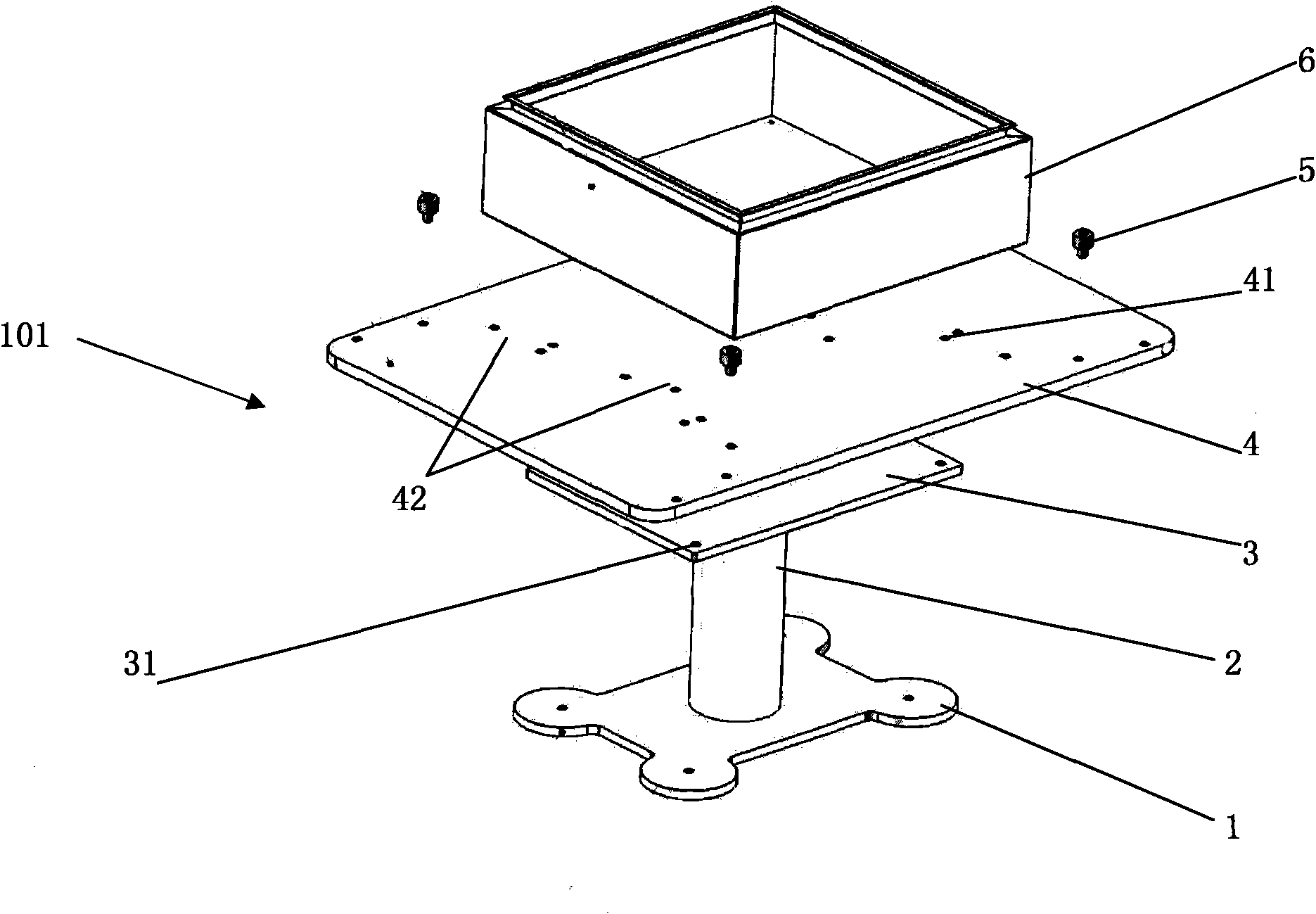
[0038] The jig 101 for automatic welding provided by Embodiment 1 of the present invention is composed of a base 1 , a bracket 2 , a connecting plate 3 , a positioning plate 4 , and a positioning shaft pin 5 . Wherein the base 1 is in the shape of a flat plate, and its four corners are provided with screw holes, and the base 1 can be fixed on the ground by passing the screws through the above screw holes. The fixed position of the base 1 is determined according to the position of the automatic welding device. The base 1 needs Within the working range of the movable arm fixed to the automatic welding device, it is preferable to set the base 1 at specific coordinates so that the automatic welding device can work in an optimal manner. The support frame 2 is fixed on the base 1, and the height of the support frame 2 is adjustable so as to adjust the height of the connecting plate 3 above the support frame 2. The connecting plate 3 is fixed on the top of the brace 2, the connecting...
Embodiment 2
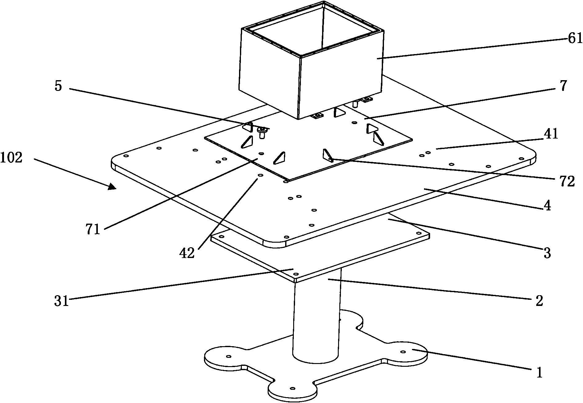
[0041] A jig 102 for automatic welding provided by the present invention is composed of a base 1 , a bracket 2 , a connecting plate 3 , a positioning plate 4 , a positioning shaft pin 5 and a fixed plate 7 . Wherein the base 1 is in the shape of a flat plate, and its four corners are provided with screw holes, and the base 1 can be fixed on the ground by passing the screws through the above screw holes. The fixed position of the base 1 is determined according to the position of the automatic welding device. The base 1 needs Within the working range of the movable arm fixed to the automatic welding device, it is preferable to set the base 1 at specific coordinates so that the automatic welding device can work in an optimal manner. The support frame 2 is fixed on the base 1, and the height of the support frame 2 is adjustable so as to adjust the height of the connecting plate 3 above the support frame 2. The connecting plate 3 is fixed on the top of the brace 2, the connecting p...
Embodiment 3
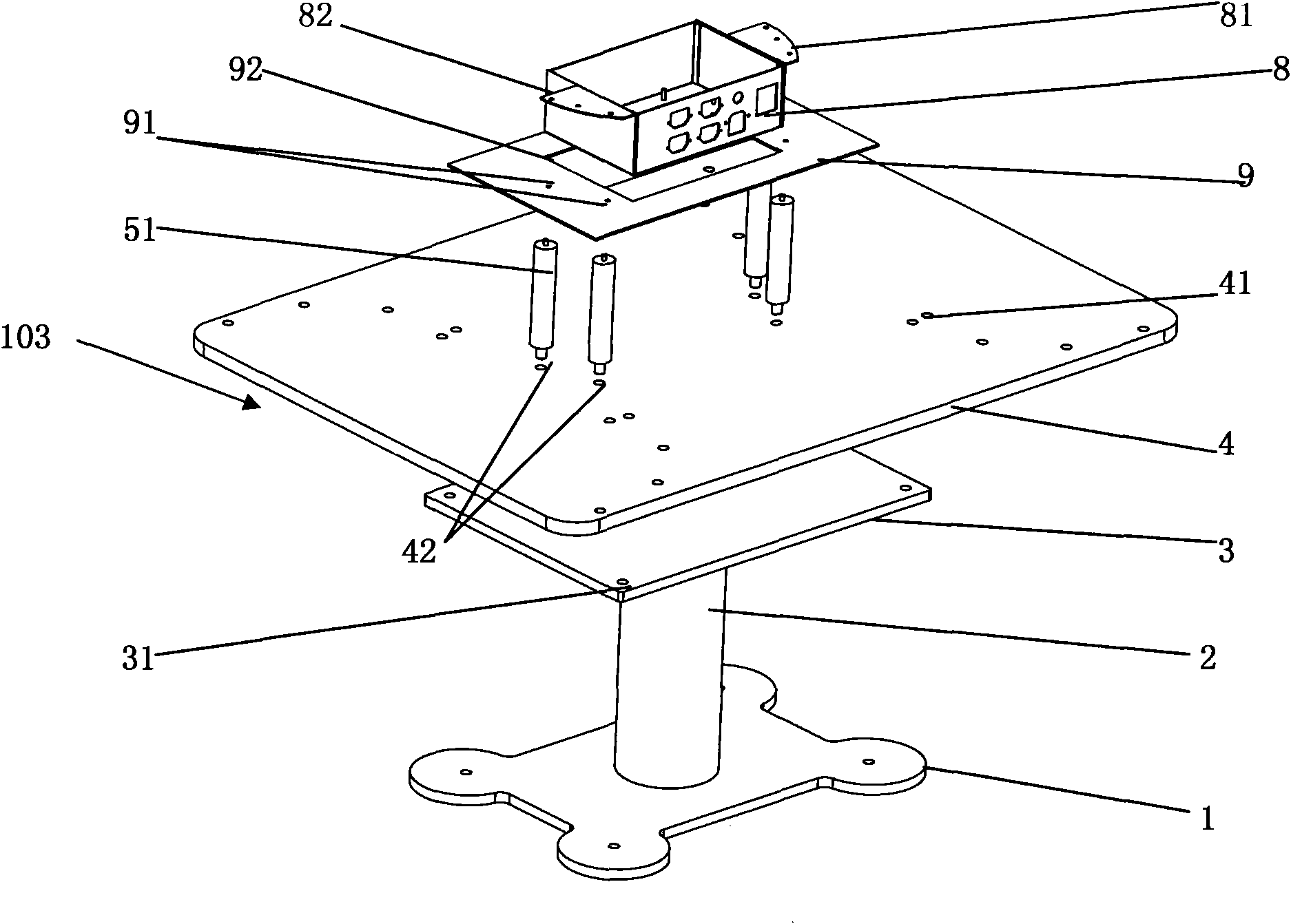
[0044] See image 3 As shown, a jig 103 for automatic welding provided by the present invention is composed of a base 1 , a bracket 2 , a connecting plate 3 , a positioning plate 4 , a positioning pivot pin 51 and a fixing plate 9 . Wherein the base 1 is in the shape of a flat plate, and its four corners are provided with screw holes, and the base 1 can be fixed on the ground by passing the screws through the above screw holes. The fixed position of the base 1 is determined according to the position of the automatic welding device. The base 1 needs Within the working range of the movable arm fixed to the automatic welding device, it is preferable to set the base 1 at specific coordinates so that the automatic welding device can work in an optimal manner. The support frame 2 is fixed on the base 1, and the height of the support frame 2 is adjustable so as to adjust the height of the connecting plate 3 above the support frame 2. The connecting plate 3 is fixed on the top of the...
PUM
 Abstract
Description
Claims
Application Information