

Physical quantity sensor, electronic device, and moving object
- Summary
- Abstract
- Description
- Claims
- Application Information
AI Technical Summary
Benefits of technology
Problems solved by technology
Method used
Image

Examples
first embodiment
[0043]A physical quantity sensor according to First Embodiment will be described with reference to FIGS. 1 to 4.
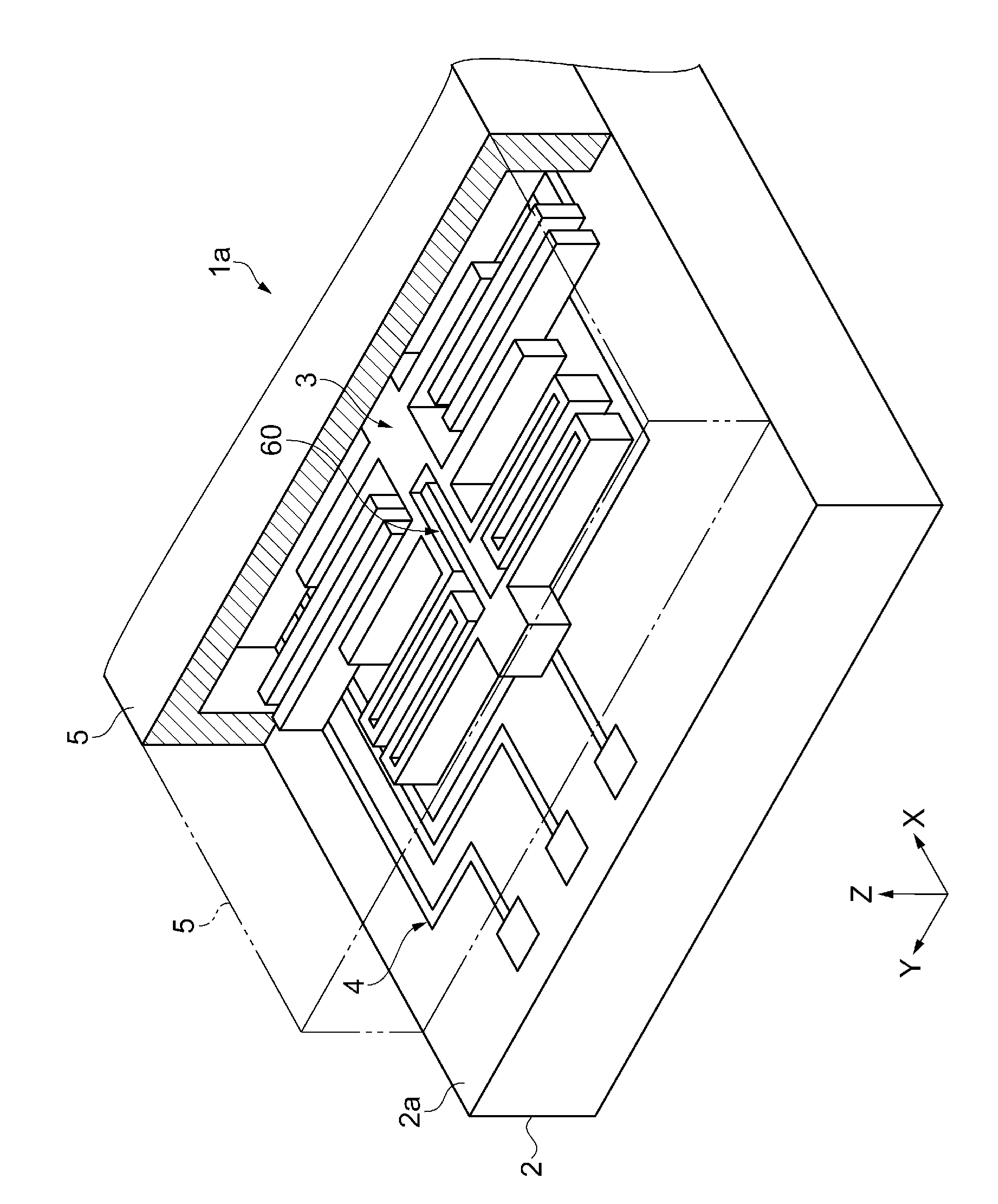
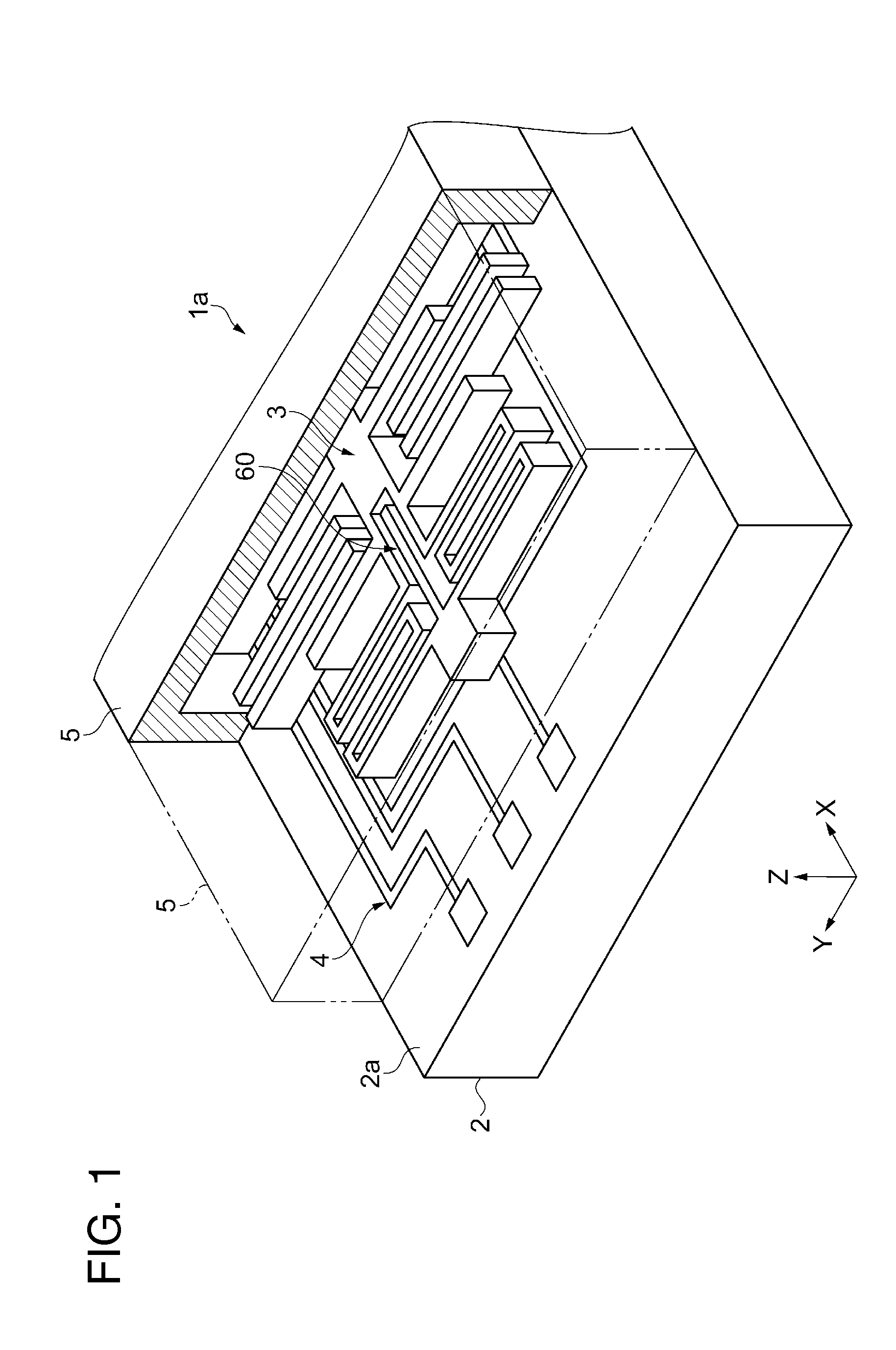
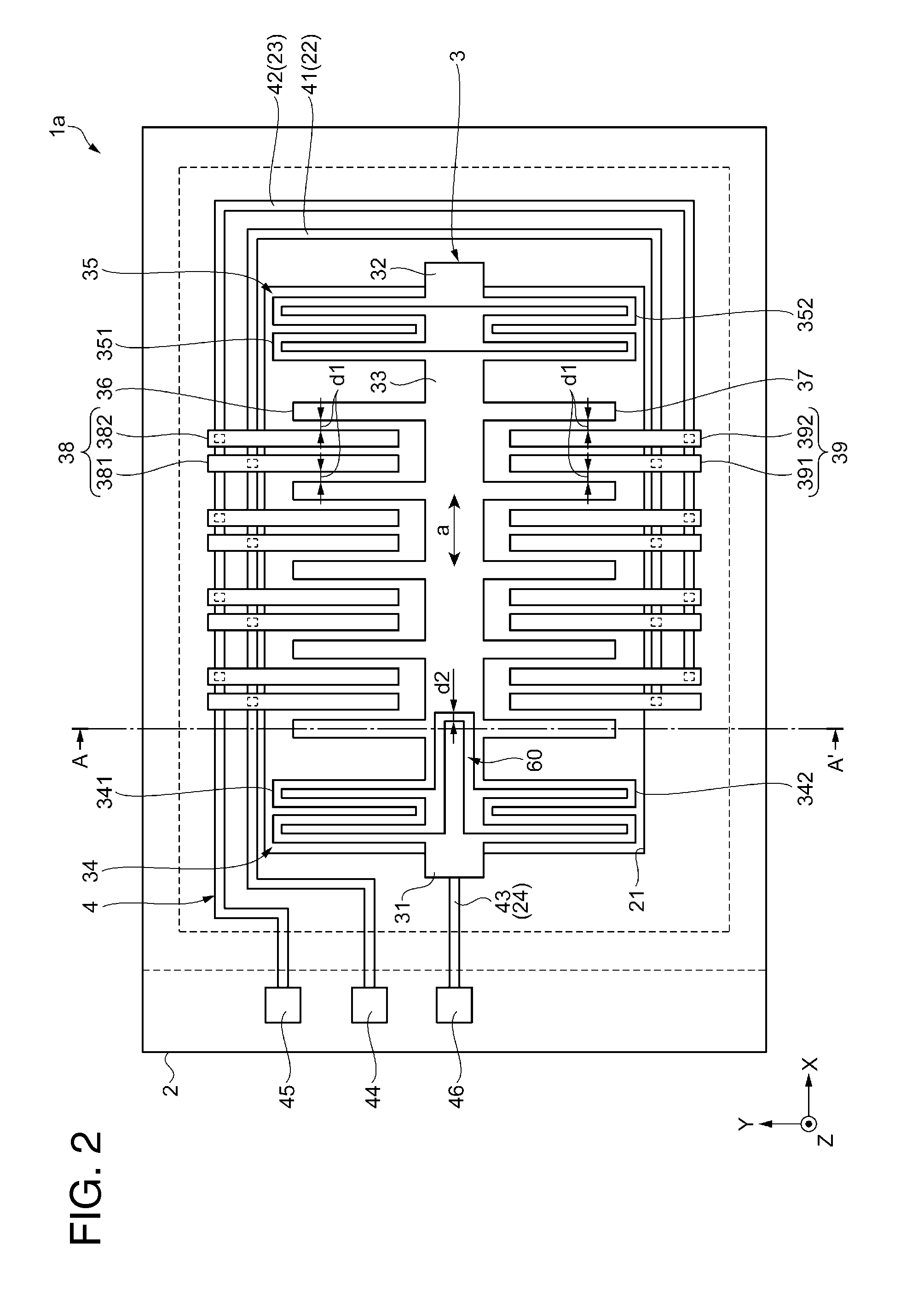
[0044]FIG. 1 is a perspective view schematically showing the physical quantity sensor according to First Embodiment. FIG. 2 is a plan view schematically showing the physical quantity sensor shown in FIG. 1. FIG. 3 is a cross-sectional view of the physical quantity sensor schematically showing a cross section taken along with line III-III of FIG. 2. FIG. 4 is a partially enlarged view of a part of a stopper portion shown in FIGS. 1 and 2. For convenience of description, a cover is omitted in FIG. 2. In addition, in FIGS. 1 to 4, an X axis, a Y axis, and Z axis are shown as three axes which are orthogonal with respect to each other, and the Z axis is an axis showing a thickness direction in which a substrate and the cover are superimposed on each other.
Structure of Physical Quantity Sensor
[0045]A physical quantity sensor 1a shown in FIG. 1 includes a substrate 2, an element ...
second embodiment
[0100]FIG. 5 is a plan view schematically showing a physical quantity sensor according to Second Embodiment.
[0101]The cover 5 is omitted in FIG. 5. In FIG. 5, an X axis, a Y axis, and Z axis are shown as three axes which are orthogonal with respect to each other, and the Z axis is an axis showing a thickness direction in which a substrate and a cover are superimposed on each other.
[0102]A physical quantity sensor 1b according to Second Embodiment is different from the physical quantity sensor 1a described in First Embodiment, in that the plurality of stopper portions 60 are provided. Since the other configurations are the same as First Embodiment, the different parts will be described and the overlapping parts will be omitted by denoting the same reference numerals.
[0103]In the same manner as the physical quantity sensor 1a described in First Embodiment, the physical quantity sensor 1b of the embodiment includes the substrate 2, the element piece 3 which is connected to (bonded to) ...
modification example 1
[0126]FIG. 6A is a partially enlarged view of a stopper portion of a physical quantity sensor according to a modification example 1.
[0127]In the same manner as the physical quantity sensors 1a and 1b described in the embodiments, in a physical quantity sensor 1c according to the modification example 1, the fixed electrode portions 38 and 39, and the movable electrode portions 36 and 37 which are provided on the movable weight 33 with the gap d1 interposed between the movable electrode portions and the fixed electrode portions 38 and 39 are provided. In addition, in the physical quantity sensor 1c according to the modification example 1, a stopper portion 160 is provided.
[0128]The physical quantity sensor 1c according to the modification example 1 has a structure of the stopper portion 160 which is different from those of the physical quantity sensors 1a and 1b described above.
[0129]In the description of the physical quantity sensor 1c according to the modification example 1, the par...
PUM
 Abstract
Description
Claims
Application Information