
Gas lighting device for an electric household appliance, in particular a cooking range, having a quick connection system to the electrodes

a gas lighting device and electric household appliance technology, applied in the direction of electric spark igniters, combustion ignition, combustion process, etc., can solve the problems of inability to ensure the correct, simultaneous, and possible deformation of the same, and achieve the effects of easy and rapid connection to the electrodes, low production and assembly costs, and small siz

Active Publication Date: 2014-07-17
ITW IND COMPONENTS SRL
View PDF2 Cites 0 Cited by
  • Summary
  • Abstract
  • Description
  • Claims
  • Application Information

AI Technical Summary

Benefits of technology

The present invention aims to improve gas lighting devices for electric household appliances such as cooking ranges by making them easier and faster to connect to the power supply wires, reducing errors and allowing for automated assembly, which lowers production and assembly costs, minimizes size, and increases operating reliability. The invention includes a frame element with pre-wired electric wires and contacts that securely connect to the electrodes, ensuring a secure and reliable connection with minimal damage to the contacts. The pre-wiring makes it possible to automatically assemble the subassemblies and reduces the risk of operator error during assembly.

Problems solved by technology

However, the assembly times of the electric wires on the high-voltage outputs of the gas lighting devices are relatively long; furthermore, due to possible incorrect manoeuvres by the assembly operator, the male and female faston connectors may not be correctly coupled, causing even possible deformations of the same.
For the same reason, the electric household appliance manufacturer cannot automatically assemble the wires onto the high-voltage outputs of the gas lighting device, because it would be essentially impossible to ensure the correct, simultaneous positioning of all male contacts with all female contacts.

Method used


Image

  • Gas lighting device for an electric household appliance, in particular a cooking range, having a quick connection system to the electrodes
  • Gas lighting device for an electric household appliance, in particular a cooking range, having a quick connection system to the electrodes
  • Gas lighting device for an electric household appliance, in particular a cooking range, having a quick connection system to the electrodes

Examples


Embodiment Construction

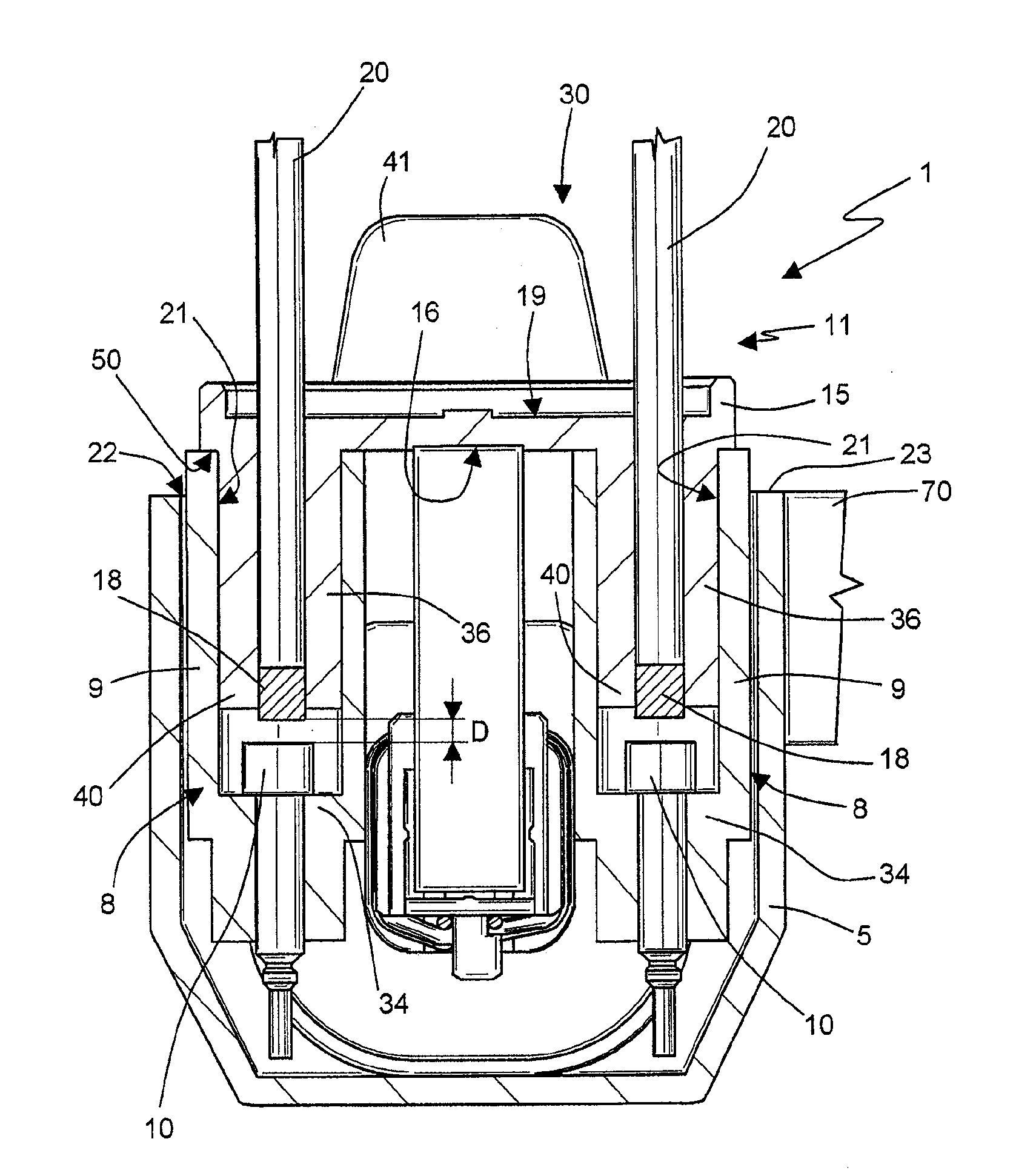
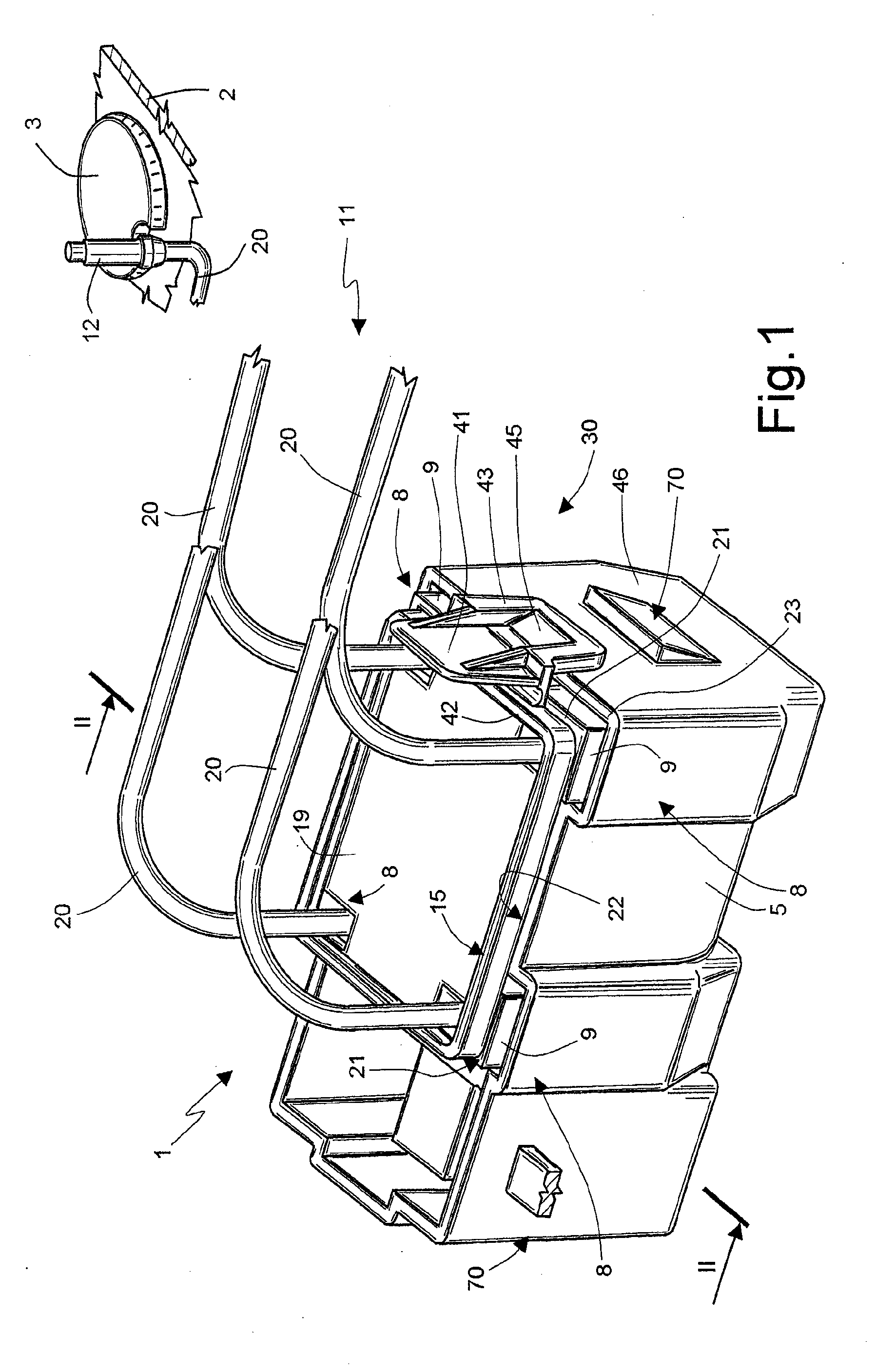
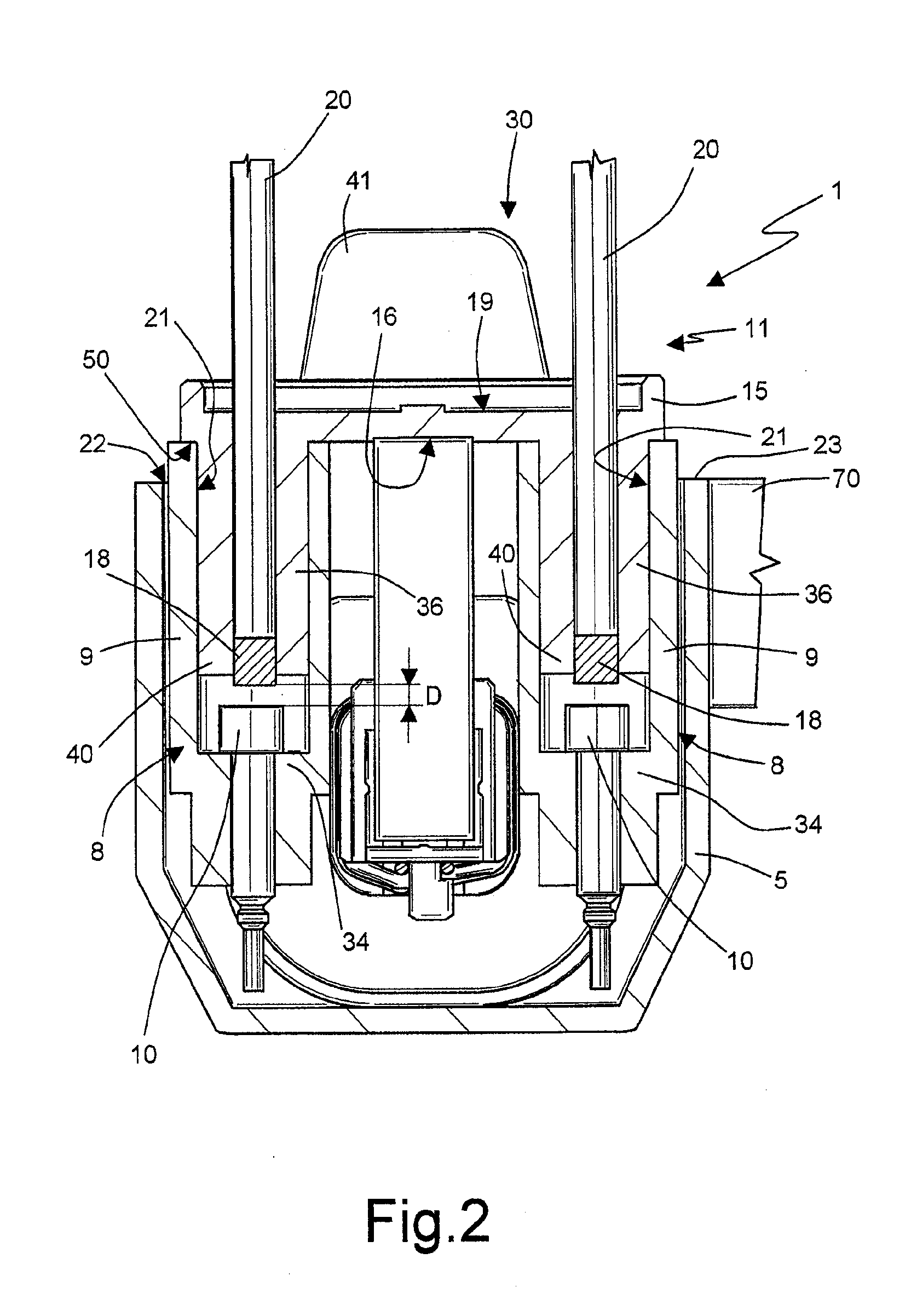
[0015]With reference to FIGS. 1 and 2, numeral 1 indicates as a whole a gas lighting device for an electric household appliance, a cooking range 2 in this non-limiting illustrated embodiment, provided with a plurality of burners 3 (only one of which is shown for the sake of simplicity); the device 1 comprises a cup-shaped casing 5, formed by an electrically insulating material, e.g. by moulding of a synthetic plastic material, and a plurality of high-voltage outputs 8 carried by the casing 5 and each comprising (FIG. 2) a chimney-like housing 9 carried by the casing 5 and also formed by an electrically insulating material and an electric contact 10 carried by the chimney-like housing 9 and arranged therein.

[0016]The gas lighting device 1 further comprises a quick connection device 11 of the high-voltage outputs 8 of the casing 5 to corresponding spark generating electrodes 12, also belonging to the gas lighting device 1 as a whole and fixable in use in a known manner, each close to ...


PUM


Abstract

An electronic gas lighting device including: a cup-shaped casing, formed by an electrically insulating material; a plurality of high-voltage outputs carried by the casing and each including a chimney-like housing carried by the casing and also formed by an electrically insulating material and a first electric contact carried by the chimney-like housing and arranged therein; and a frame element integrally and protrudingly carrying, on a first face thereof intended in use to face towards the casing, a plurality of second contacts, in number equal to the high-voltage outputs present on the casing and adapted to couple with the first contacts within said chimney-like housings, and provided on a second face thereof, opposite to the first, with a plurality of electric wires each connecting a second contact with a spark generating electrode fastenable to a cooking range; snapping fastening means to the casing being peripherally arranged on the outside of the frame element, along at least one side of the same.

Description

TECHNICAL FIELD[0001]The present invention relates to an electronic gas lighting device, of the type intended to equip an electric household appliance, such as for example a cooking range, for determining the controlled lighting of the burners by supplying a high voltage to electrodes fixable to the cooking range, provided with a quick connection device of the electrodes to the high-voltage outputs of the gas lighting device.BACKGROUND ART[0002]It is known from EP1101067B1, to the same Applicant, an electronic gas lighting device including a casing formed by electrically insulating material provided with a plurality of high-voltage outputs each defined by a chimney-like housing, integrally obtained with the casing and carrying a corresponding high-voltage contact therein, e.g. a male faston connector. In use, each contact in the chimney-like housings must be connected, by means of an electric wire, to a corresponding spark generating electrode, fixable to the cooking range at a burn...

Claims


Application Information

Patent Timeline
Patent Type & Authority Applications(United States)
IPC IPC(8): F23Q3/00
CPCF23Q3/006F23Q3/00
Inventor PIANEZZE, DANIELEALEARDI, MASSIMO
Owner ITW IND COMPONENTS SRL
Learn More