Acoustic wave drying system

Active Publication Date: 2014-07-24
EASTMAN KODAK CO
View PDF1 Cites 7 Cited by
  • Summary
  • Abstract
  • Description
  • Claims
  • Application Information

AI Technical Summary

Benefits of technology

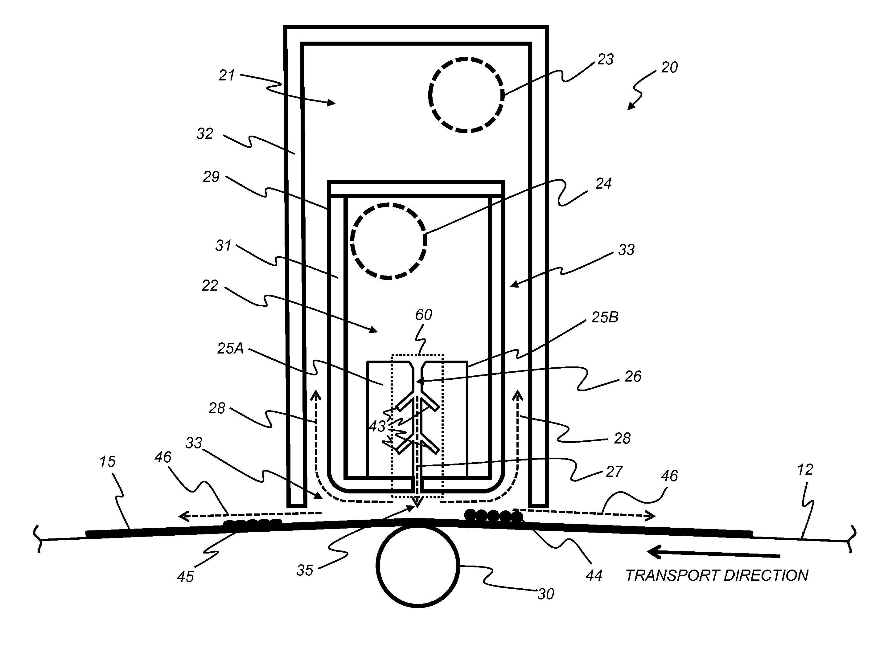
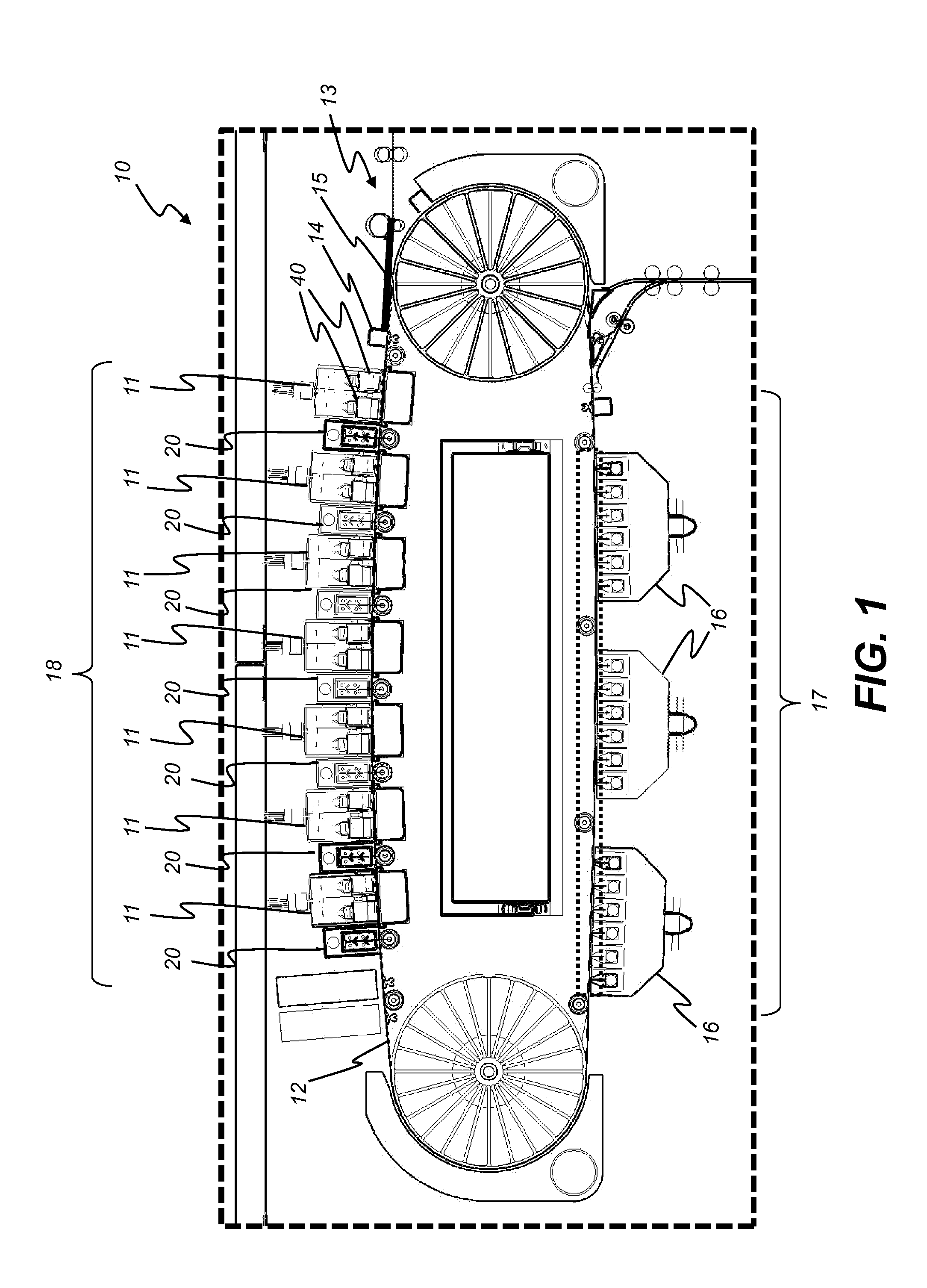
The invention uses a combination of heat and air flow to accelerate drying, with the addition of acoustic energy to disrupt the boundary layer. This allows for faster drying in a smaller area, making the dryer more compact. The system creates high sound pressure levels that accelerate drying while the air flow velocity remains low to prevent damage to the liquid coating.

Problems solved by technology

High sound pressure levels are necessary to accelerate the drying process, but the high airstream velocities that are normally associated with such high sound pressure levels can disrupt the liquid coating and cause undesirable image artifacts or coating defects.

Method used


Image

  • Acoustic wave drying system
  • Acoustic wave drying system
  • Acoustic wave drying system

Examples


Embodiment Construction

[0024]The invention is inclusive of combinations of the embodiments described herein. References to “a particular embodiment” and the like refer to features that are present in at least one embodiment of the invention. Separate references to “an embodiment” or “particular embodiments” or the like do not necessarily refer to the same embodiment or embodiments; however, such embodiments are not mutually exclusive, unless so indicated or as are readily apparent to one of skill in the art. The use of singular or plural in referring to the “method” or “methods” and the like is not limiting. It should be noted that, unless otherwise explicitly noted or required by context, the word “or” is used in this disclosure in a non-exclusive sense.

[0025]The present invention will be directed in particular to elements forming part of, or in cooperation more directly with the apparatus in accordance with the present invention. It is to be understood that elements not specifically shown or described m...


PUM


Abstract

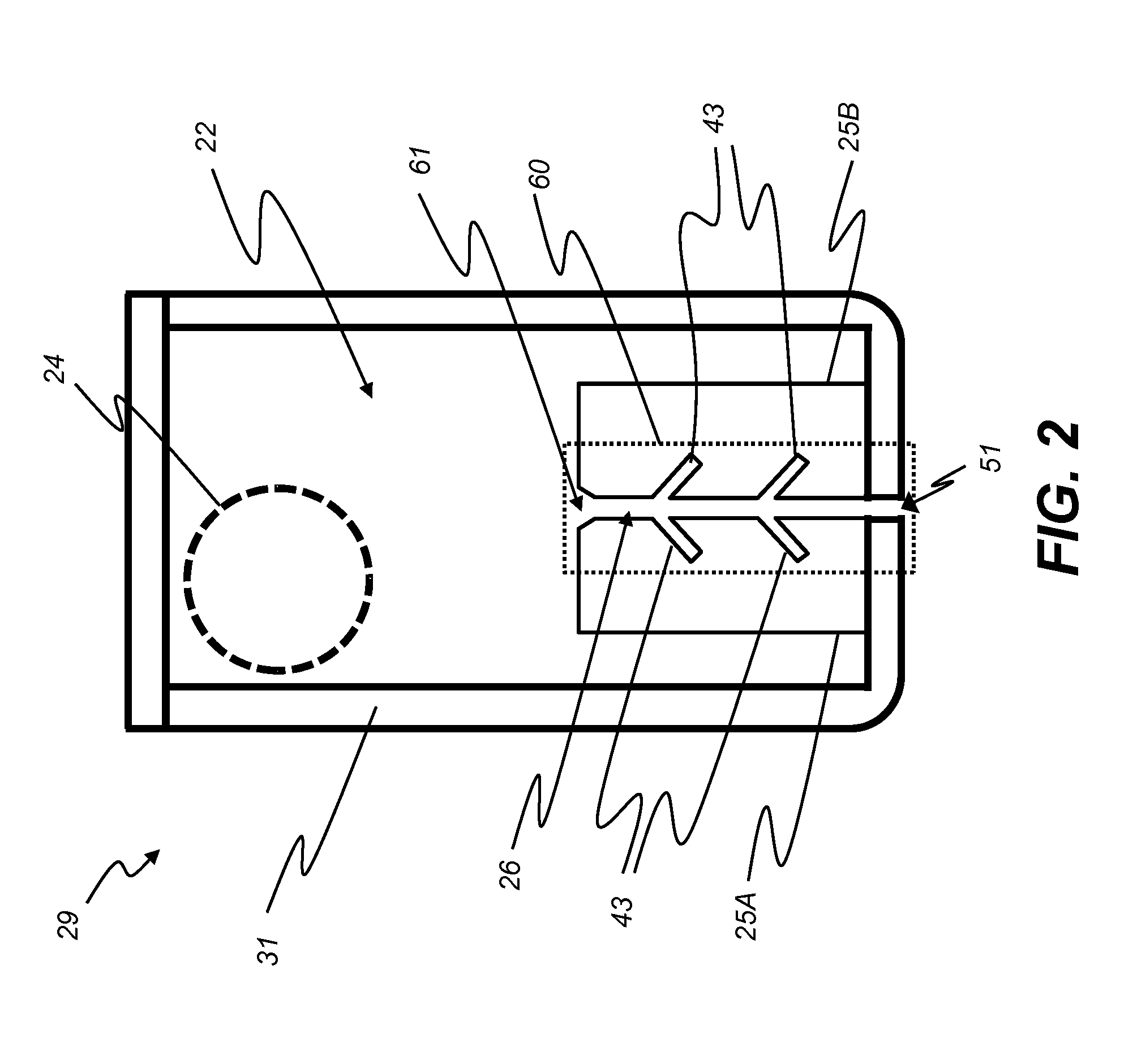
An acoustic wave drying system for drying a material using an acoustic resonant chamber that imparts acoustic energy to transiting air received from an airflow source. The acoustic resonant chamber includes a primary air channel having side surfaces connecting an air inlet and an air outlet, the primary air channel having a primary air channel length between the air inlet and the air outlet. One or more secondary closed-end resonant chambers are formed into side surfaces of the primary air channel. An air impingement airstream containing acoustic energy exits the air outlet and impinges on the material.

Description

CROSS-REFERENCE TO RELATED APPLICATIONS[0001]Reference is made to commonly assigned, co-pending U.S. patent application Ser. No. ______ (K000958), entitled: “Acoustic drying system with matched exhaust flow”, by Shifley et al.; and to commonly assigned, co-pending U.S. patent application Ser. No. ______ (K001144), entitled: “Acoustic drying system with peripheral exhaust conduits”, by Bucks et al.; to commonly assigned, co-pending U.S. patent application Ser. No. ______ (Docket K001245), entitled: “Acoustic wave drying method”, by Bucks et al.; to commonly assigned, co-pending U.S. patent application Ser. No. ______ (Docket K001142), entitled: “Acoustic drying system with sound outlet channel”, by Bucks et al.; and to commonly assigned, co-pending U.S. patent application Ser. No. ______ (Docket K001244), entitled: “Acoustic drying method using sound outlet channel”, by Bucks et al., each of which is incorporated herein by referenceFIELD OF THE INVENTION[0002]The present invention re...

Claims


Application Information

Patent Timeline
IPC IPC(8): F26B7/00
CPCB41J11/002F26B5/02F26B7/00B41J11/0022
Inventor BUCKS, RODNEY RAYCIASCHI, ANDREWMARCUS, MICHAEL ALANNG, KAM CHUEN
Owner EASTMAN KODAK CO
Why Eureka
Try Eureka