
High Bandwidth Sonic Tone Generation

Active Publication Date: 2019-03-28
LISNR
View PDF7 Cites 12 Cited by
  • Summary
  • Abstract
  • Description
  • Claims
  • Application Information

AI Technical Summary

Benefits of technology

The patent describes a device that can generate and send out a sonic signal that carries a digital message. This is done by generating a sequence of symbols that are associated with time periods when two different carriers are transmitting at different frequencies. The system then creates an audio sample of this symbol sequence and controls the audio device to send out the sonic signal. The technical effect of this technology is that it allows for the creation of unique and interesting sonic signals that can be used as audio content.

Problems solved by technology

The previously described systems for producing sonic signals have a number of limitations, specifically in the integrity of data transmission, and in the flexibility of the system to efficiently transmit relatively large amounts of data, and data of different volumes for different applications.

Method used


Image

  • High Bandwidth Sonic Tone Generation
  • High Bandwidth Sonic Tone Generation
  • High Bandwidth Sonic Tone Generation

Examples


Embodiment Construction

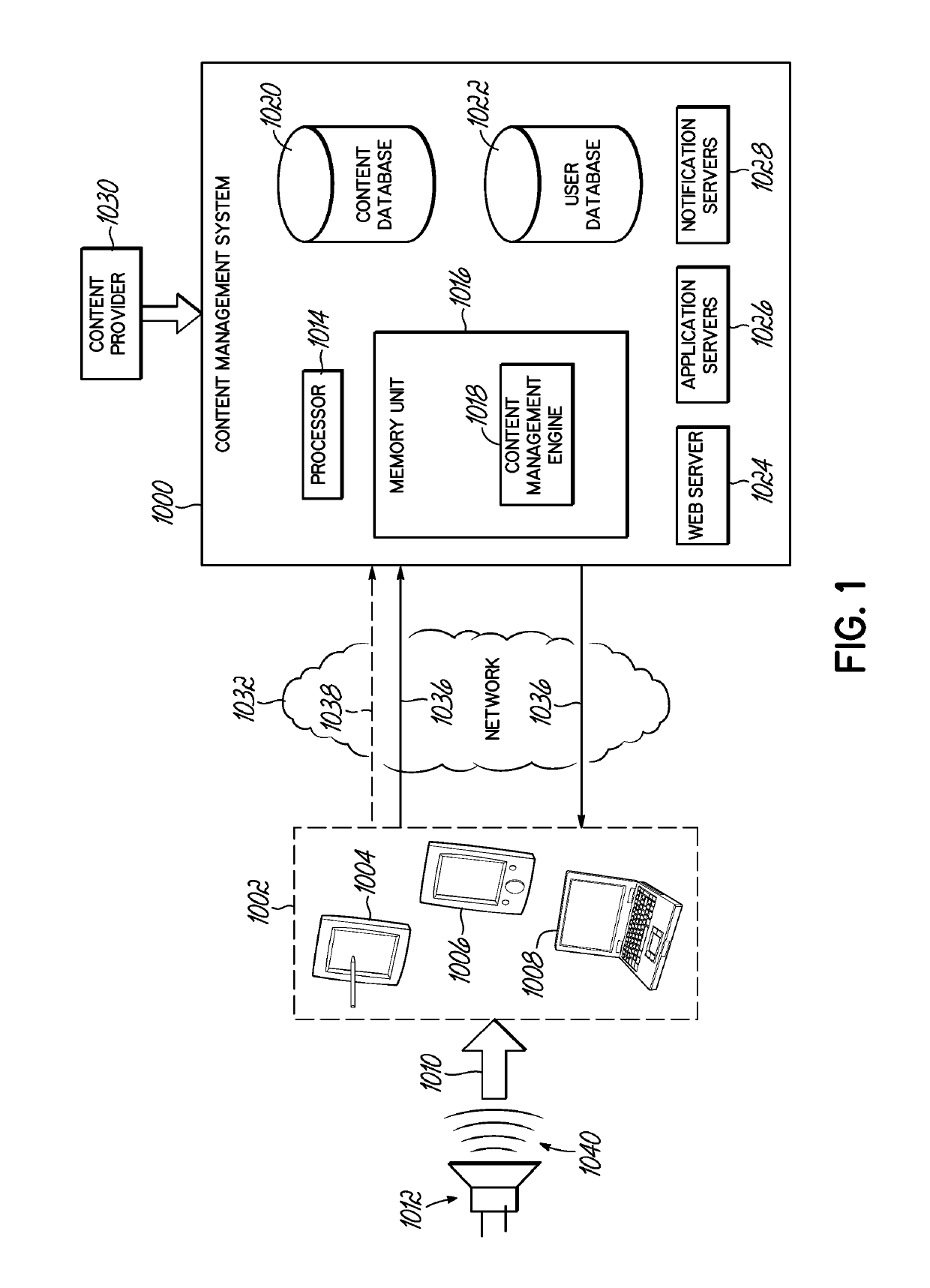
[0019]Various non-limiting embodiments of the invention are described to provide an understanding of the principles of the structure, function, and use of the content delivery and management systems and processes disclosed herein. One or more examples of these non-limiting embodiments are illustrated in the accompanying drawings. Persons of ordinary skill in the art will understand that systems and methods specifically described herein and illustrated in the accompanying drawings are non-limiting embodiments. The features illustrated or described in connection with one non-limiting embodiment may be combined with the features of other non-limiting embodiments. Such modifications and variations are intended to be included within the scope of this disclosure.

[0020]Reference throughout the specification to “various embodiments,”“some embodiments,”“one embodiment,”“some example embodiments,”“one example embodiment,” or “an embodiment” means that a particular feature, structure, or chara...


PUM


Abstract

A sonic signal encodes a symbol sequence representing a binary message, for delivery as audio content. The binary message into a sequence of symbols that are each associated with frequency characteristics transmitted over a time period. Two carriers are transmitted at two selected frequencies during each time period, delivering the binary data at a high rate. The symbol sequence is preceded by a prefix which takes the form of a sweeping frequency tone which sweeps over the frequency ranges of the carriers. Further, the amplitudes of the carriers are adjusted so that higher frequency transmissions are transmitted at higher sound pressure levels. Methods for synchronizing to the symbol sequence and decoding the symbol sequence are also described.

Description

CROSS REFERENCE TO RELATED APPLICATION[0001]This application is related to PCT Application Serial No. US2013 / 039079 filed May 1, 2013, which was published in the United States on Apr. 23, 2015 as Publication US2015-0113094, and which claims benefit of US Provisional Patent Application Ser. Nos. 61 / 781,107 filed Mar. 14, 2013 and 61 / 640,900 filed May 1, 2012, each of which is incorporated herein by reference in its entirety.[0002]This application is also related to PCT Application Serial No. US2015 / 055738 filed Oct. 15, 2015, which claims benefit of U.S. Provisional Patent Application Ser. No. 62 / 064,468 filed Oct. 15, 2014, which is incorporated herein in its entirety.[0003]This application is also related to PCT Application Serial No. US2017 / 024025 filed Mar. 24, 2017, which claims benefit of U.S. patent application Ser. No. 15 / 081,158 filed Mar. 25, 2016, which is incorporated herein in its entirety.TECHNICAL FIELD[0004]This application generally relates to systems and methods for...

Claims


Application Information

Patent Timeline
IPC IPC(8): G10L19/018G10L19/02
CPCG10L19/018G10L19/02H04B11/00G01L19/02
Inventor KNAUER, WILLIAMFARRAR, REBEKAH L.
Owner LISNR
Learn More