Ultrasonic Transducer and Ultrasonic Speaker Using the Same

Inactive Publication Date: 2007-10-18
SEIKO EPSON CORP
View PDF9 Cites 14 Cited by
  • Summary
  • Abstract
  • Description
  • Claims
  • Application Information

AI Technical Summary

Benefits of technology

[0025] In view of the above situation, it is an object of the present invention to provide an ultrasonic transducer that can generate an acoustic signal of a sound pressure level sufficiently high to obtain the parametric array effect over a wide frequency band, and an ultrasonic speaker using the same.

Problems solved by technology

Hence the sound pressure is slightly insufficient for using it as an ultrasonic speaker.
Since the speed of sound is fast in the dense parts and is slow in the sparse parts, a distortion occurs in the modulated wave itself.
An ultrasonic sound pressure of not lower than 120 dB is necessary in order that the parametric array effect appears sufficiently, but it is difficult to achieve this figure by the electrostatic ultrasonic transducer.
It can be easily understood that it is difficult to reproduce (demodulate) the broadband of 20 kHz with fidelity with the resonant ultrasonic speaker using the conventional piezoelectric element.
Actually, the ultrasonic speaker using the conventional resonant ultrasonic transducer shown in FIG. 6 has the following problems: (1) the band is narrow and reproduced sound quality is low; (2) if the AM modulation factor is too high, the demodulated sound is distorted, and hence the modulation factor can be increased up to about 0.5 at maximum; (3) if the input voltage is increased (if the volume is increased), vibration of the piezoelectric element becomes unstable, and the sound is distorted When the voltage is further increased, the piezoelectric element itself is likely to be broken; and (4) arraying, enlargement, and miniaturization are difficult, and hence the production cost is high.
However there is a problem in that the absolute sound pressure is not sufficient for the demodulated sound to have sufficient volume.
Therefore, there is a problem in that when the Pull-type ultrasonic transducer is used for the ultrasonic speaker, vibration of the vibrating film directly generates audible sound.

Method used


Image

  • Ultrasonic Transducer and Ultrasonic Speaker Using the Same
  • Ultrasonic Transducer and Ultrasonic Speaker Using the Same
  • Ultrasonic Transducer and Ultrasonic Speaker Using the Same

Examples


Embodiment Construction

[0083] An embodiment of the present invention will be described in detail with reference to the drawings.

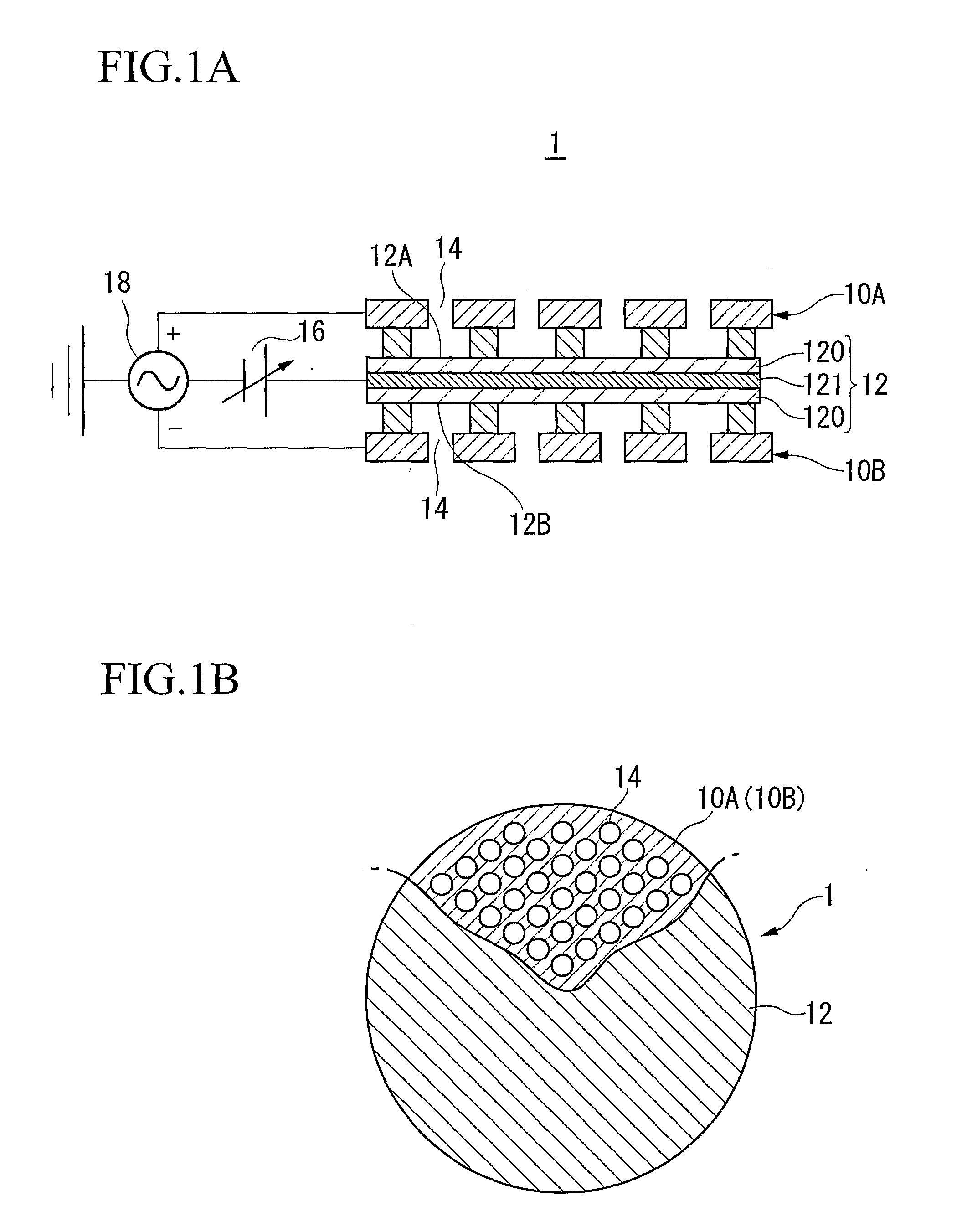
[0084] In FIGS. 1A and 1B, the ultrasonic transducer 1 according to the embodiment comprises: a pair of fixed electrodes 10A and 10B including a conductive member formed of a conductive material, which functions as an electrode; a vibrating film 12 having a conductive layer 121 and clamped between the pair of fixed electrodes; and a member (not shown in FIG. 1A or 1B but substantially the same structure as the case 130 shown in FIG. 7) which holds the pair of fixed electrodes 10A and 10B and the vibrating film 12. The pair of fixed electrodes 10A and 10B may be referred to as first and second fixed electrodes 10A and 10B, respectively, hereinafter.

[0085] The vibrating film 12 is formed of nonconductive bodies 120 and has an electrode layer 121 formed of a conductive material. The electrode layer 121 is applied with a DC bias voltage of a single polarity (which may be a positive...


PUM


Abstract

An ultrasonic transducer includes: a pair of fixed electrodes including a conductive member; a vibrating film having a conductive layer; and a member which holds the pair of fixed electrodes and the vibrating film. The vibrating film is formed of nonconductive bodies and has an electrode layer formed of a conductive material. The electrode layer is applied with a DC bias voltage of a single polarity by a DC bias supply, and is also applied with an AC signal output from a signal source superimposed on the DC bias voltage. The pair of fixed electrodes have a plurality of holes of the same number at positions facing each other via the vibrating film, and an AC signal is applied between the conductive members of the pair of fixed electrodes by the signal source.

Description

TECHNICAL FIELD [0001] The present invention relates to an electrostatic ultrasonic transducer that generates a constant high sound pressure over a wide frequency band, and an ultrasonic speaker using the same. [0002] Priority is claimed on Japanese Patent Application No. 2004-173946, filed Jun. 11, 2004, the content of which is incorporated herein by reference. BACKGROUND ART [0003] The configuration of a conventional ultrasonic transducer is shown in FIG. 6. Most conventional ultrasonic transducers are resonant ultrasonic transducers using a piezoelectric ceramic as a vibrating element. The ultrasonic transducer shown in FIG. 6 uses the piezoelectric ceramic as the vibrating element to perform both conversion from an electric signal to ultrasonic waves and conversion from ultrasonic waves to the electric signal (transmission and reception of ultrasonic waves). The bimorph-type ultrasonic transducer shown in FIG. 6 comprises two piezoelectric ceramics 61 and 62, a cone 63, a case 6...

Claims


Application Information

Patent Timeline
IPC IPC(8): H04R19/00H04R17/00H04R3/00H04R17/10
CPCH04R2217/03H04R17/005
Inventor MATSUZAWA, KINYASEKINO, HIROKAZUFUKUI, YOSHIKIMIYAZAKI, SHINICHI
Owner SEIKO EPSON CORP
Why Eureka
Try Eureka