High sound pressure alarm buzzer

A buzzer and high-pitched technology, which is applied to sirens, sounding devices, instruments, etc., can solve the problem that the alarm buzzer cannot emit high sound pressure, and achieve increased stability and safety, a strong sense of urgency, and sound rush effect

Inactive Publication Date: 2014-04-09
XINGHUA HUAXING MACHINERY & ELECTRONICS
View PDF0 Cites 6 Cited by
  • Summary
  • Abstract
  • Description
  • Claims
  • Application Information

AI Technical Summary

Problems solved by technology

[0003] The purpose of the present invention is to provide a high sound pressure alarm buzzer, which solves the problem that the alarm buzzer cannot emit high sound pressure

Method used


Image

  • High sound pressure alarm buzzer

Examples


Embodiment Construction

[0009] In order to deepen the understanding of the present invention, the present invention will be described in further detail below in conjunction with examples. The examples are only used to explain the present invention and do not constitute a limitation on the protection scope of the present invention.

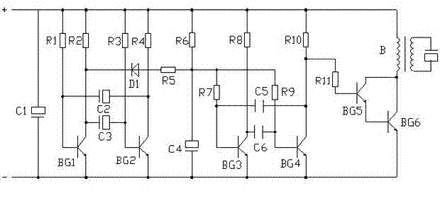
[0010] Such as figure 1 As shown, this embodiment provides a high sound pressure alarm buzzer, including a buzzer and a control circuit, the control circuit includes 11 resistors R1~R11, 6 electrolytic capacitors C1~C6, and 6 transistors BG1 ~BG6, diode D1 and transformer B1, the electrolytic capacitor C1 is connected in series between the positive and negative electrodes of the power supply; the transistors BG1~BG6 are arranged between the positive and negative electrodes of the power supply, and the base of the triode BG1 is connected to The power supply is positive, the collector of the transistor BG1 is connected to the positive electrode through the resistor R2, the emi...


PUM


Abstract

The invention provides a high sound pressure alarm buzzer which comprises a buzzer and a control circuit. The control circuit comprises 11 resistors, 6 electrolytic capacitors, 6 triodes, a diode and a transformer. The high sound pressure alarm buzzer provided by the invention has the advantages of high sound pressure level, rushed sound, strong sense of urgency, small volume and light weight, and is applicable to all kinds of alarm situations. The stability and the safety of a device are improved.

Description

Technical field [0001] The invention relates to an alarm buzzer, in particular to a high sound pressure alarm buzzer. Background technique [0002] At present, the existing alarm buzzer is limited in size and cannot provide high sound pressure. It is not suitable for some specific occasions, such as anti-theft, fire prevention, gas leakage, emergency rescue, call for help, and strong reminders. Sound equipment, etc., cause the person who needs to be reminded to be unable to hear the prompt sound, and then unable to take due protective measures, causing losses. Therefore, develop a small size and high sound pressure. An alarm buzzer with a stable circuit is particularly important. Summary of the invention [0003] The purpose of the present invention is to provide a high sound pressure alarm buzzer, which solves the problem that the alarm buzzer cannot emit high sound pressure. [0004] The present invention provides a high sound pressure alarm buzzer, including a buzzer and a con...

Claims


Application Information

Patent Timeline
Patent Type & Authority Applications(China)
IPC IPC(8): G10K9/12G10K7/00G08B3/10
Inventor 黄骐
Owner XINGHUA HUAXING MACHINERY & ELECTRONICS
Why Eureka
Try Eureka