Fuel injection system having a fuel-carrying component, a fuel injector and a connecting element

Inactive Publication Date: 2014-07-24
ROBERT BOSCH GMBH
View PDF2 Cites 3 Cited by
  • Summary
  • Abstract
  • Description
  • Claims
  • Application Information

AI Technical Summary

Benefits of technology

[0011]Another advantage is a simple installation of the connecting element. In particular, no pre-assembly of the connecting element on the fuel injector or the fuel-carrying component is required. In particular, the fuel injector may first be placed on the fuel-carrying component and then the connecting element may be suitably attached.
[0012]It is advantageous for the base body to have a connecting web and for the first arm and the second arm to be connected to each other via the connecting web. It is furthermore advantageous in this regard that at least the first arm of the base body and/or at least the second arm of the base body and/or at least the connecting web of the base body is/are formed at least partially from an elastic material. Specifically, the entire base body may be formed at least partially from an elastic material. This makes it possible to implement a decoupling between the first contact surface and the second contact surface, it being possible to specify the desired stiffness in a targeted manner.
[0013]It is furthermore advantageous in this regard that at least the first arm of the base body and/or at least the second arm of the base body and/or at least the connecting web of the base body is/are formed from multiple layers, a portion of the layers being formed from an elastic material. The other portion of the layers may be formed from a metallic material. This makes it possible, on the one hand, to achieve a desired elasticity. On the other hand, a sufficient stability may be ensured over the service life. The layer construction also ensures that the stability required for absorbing the retention forces is always guaranteed.
[0014]It is also advantageous, however, that the first contact surface is developed on a metallic layer, that the second contact

Problems solved by technology

The development of the fuel injection device known from German Published Patent Application No. 10 2005 020 380 has the disadvantage that vibrations may be transmitted from the fuel injector to the connection fitting via the connecting part that is developed as a pot-shaped sleeve.
In particular, structure-borne noise may be transmitted as a result via the connecting part.
This worsens a noise behavior.
Specifically in the case of electromagnetic high-pressure fuel inject

Method used


Image

  • Fuel injection system having a fuel-carrying component, a fuel injector and a connecting element
  • Fuel injection system having a fuel-carrying component, a fuel injector and a connecting element
  • Fuel injection system having a fuel-carrying component, a fuel injector and a connecting element

Examples


Example

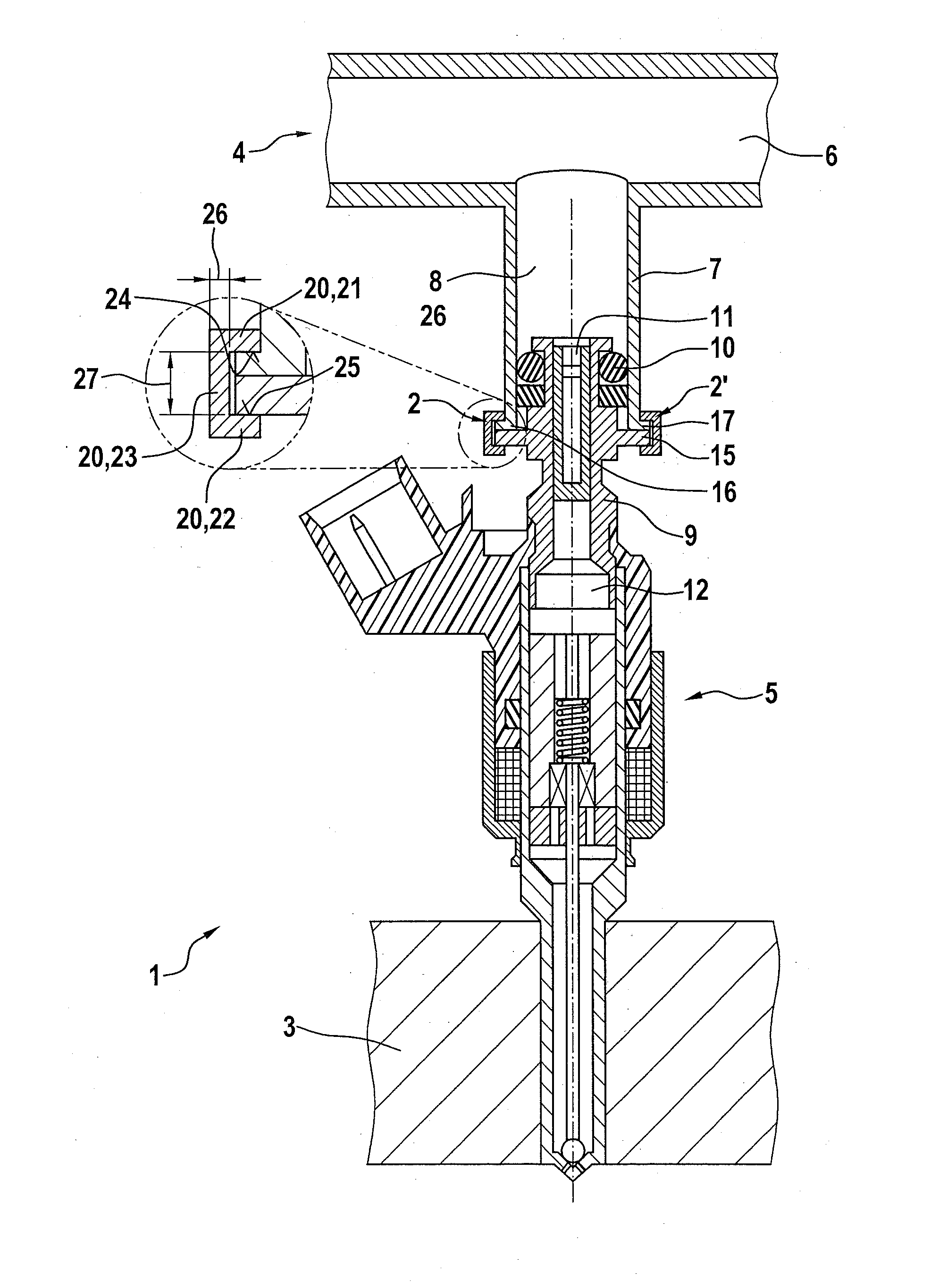
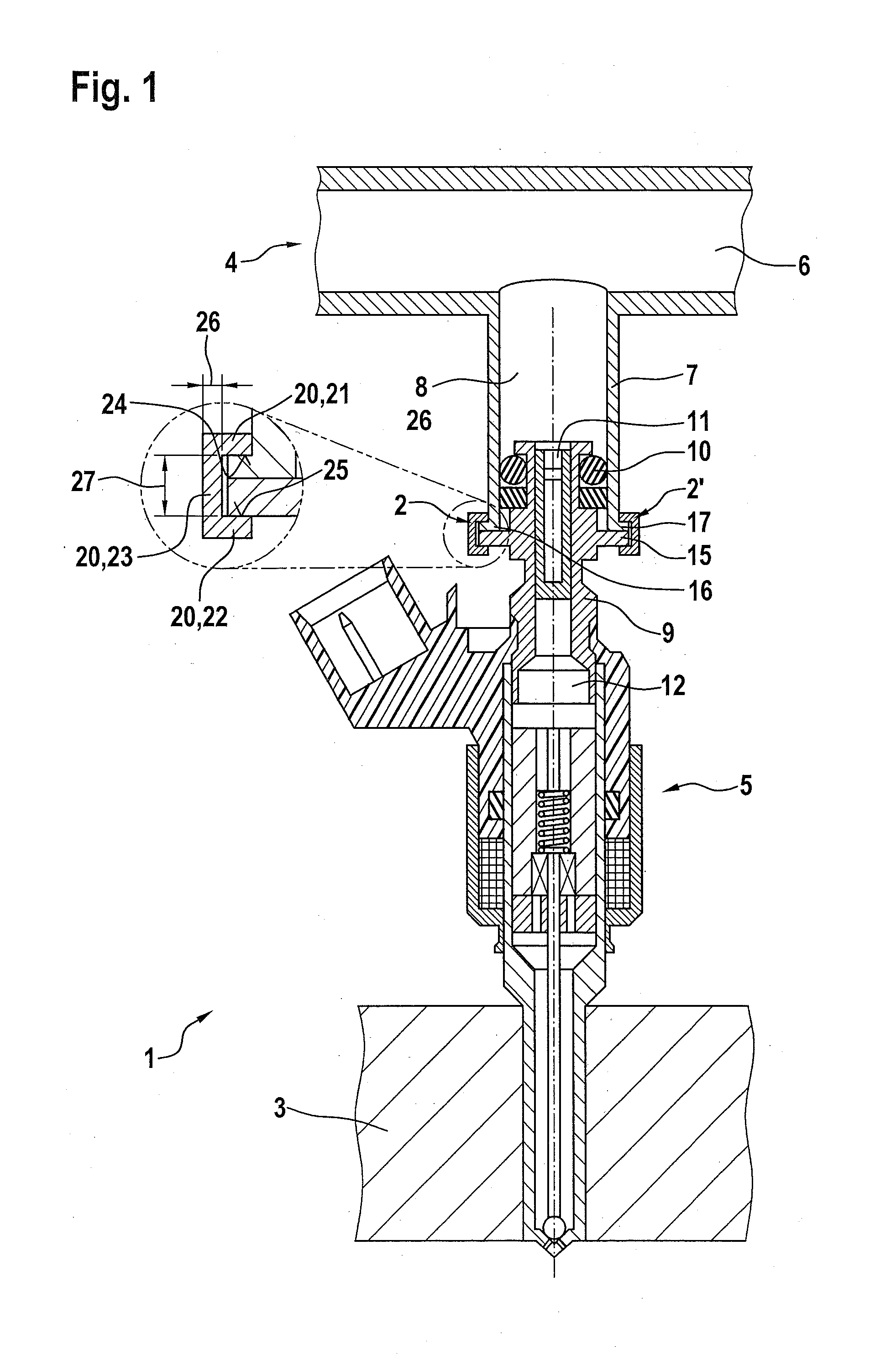
[0020]FIG. 1 shows a fuel injection system 1 having a connecting element 2 corresponding to a first exemplary embodiment and an internal combustion engine 3 in an excerpted, schematic sectional view. In this exemplary embodiment, fuel injection system 1 has a fuel-carrying component 4, which is designed as a fuel distributor rail 4. Fuel injection system 1 may be particularly used for high-pressure injection in internal combustion engines 3. In particular, fuel injection system 1 may be used in mixture-compressing internal combustion engines 3 having externally supplied ignition. Connecting element 2 is particularly suitable for such a fuel injection system 1. For this purpose, fuel distributor rail 4 is able to store fuel at high pressure and distribute it to multiple fuel injectors 5, of which only fuel injector 5 is shown in FIG. 1 for the sake of simplifying the representation.

[0021]Fuel distributor rail 4 has an elongated fuel chamber 6, via which fuel may be conveyed into a cu...


PUM


Abstract

A connecting element for fuel injection systems is used for connecting a fuel injector to a fuel-carrying component. For this purpose, the connecting element has a base body, which is connected on the one side in a form-locking manner to the fuel-carrying component and on the other side is connected in a form-locking manner to the fuel injector. The base body is developed as a bracket-shaped base body, the base body having a first arm, a second arm and a connecting web. The base body abuts on a first contact surface, which is provided on the first arm, on the one side against the fuel-carrying component and on a second contact surface, which is provided on the second arm, on the other side against the fuel injector. An elastic decoupling is provided between the first contact surface and the second contact surface. Furthermore, a fuel injection system having a fuel-carrying component, a fuel injector and such a connecting element is indicated.

Description

FIELD OF THE INVENTION[0001]The present invention relates to a connecting element for fuel injection systems for connecting a fuel injector to a fuel-carrying component, and it relates to a fuel injection system having such a connecting element. The present invention specifically relates to the field of fuel injection systems for mixture-compressing internal combustion engines having externally supplied ignition.BACKGROUND INFORMATION[0002]German Published Patent Application No. 10 2005 020 380 describes a fuel injection device, which is characterized by a noise-decoupling construction. The known fuel injection device includes a fuel injector, a receiving borehole for the fuel injector in a cylinder head and a fuel distributor line having a connection fitting, into which the fuel injector is inserted in a partially overlapping manner. In one possible development, a connecting part is developed as a pot-shaped sleeve, which is situated securely and solidly on the downstream end of th...

Claims


Application Information

Patent Timeline
IPC IPC(8): F02M55/00
CPCF02M55/005F02M61/14F02M2200/856
Inventor FISCHER, MICHAELKNORPP, MICHAELRIEMER, MARTINHORST, HANS-GEORGGLASER, ANDREASROGLER, PHILIPPHERRMANN, JANREHWALD, ANDREASMAYER, MICHAELSCHEEF, VOLKERREINHARDT, WILHELM
Owner ROBERT BOSCH GMBH
Why Eureka
Try Eureka