Multi-Direction Variable Optical Transceiver

a transceiver and variable technology, applied in the field of optical networks, can solve the problems of insufficient use of advanced technologies listed above, insufficient effectiveness of conventional intensity modulation used in 10 gb/s or below systems, and often under-utilized, so as to achieve the effect of flexible network

Active Publication Date: 2014-07-24
NEC CORP
View PDF1 Cites 91 Cited by
  • Summary
  • Abstract
  • Description
  • Claims
  • Application Information

AI Technical Summary

Benefits of technology

[0024]The present invention is directed to an optical transceiver including a multi-direction variable transmitter; and a multi-direction variable receiver, the transmitter including multiple outputs with different subcarriers being directed to different ones of the outputs to go to different directions in a network, the receiver including receiving multiple inputs, thereby enabling transmission direction in a network with the transceiver at subcarrier granularity and avoiding entire super-channel granularity and enabling unused subcarriers to be utilized for traffic in other directions or destinations and making switching granularity finer for flexibility in the network.
[0025]In an alternative expression of the invention, a method by a transceiver in an optical network includes a multi-direction variable transmitter with multiple outputs and different subcarriers for directing different ones of the outputs to go to different directions in the network, and a multi-direction variable receiver for receiving multiple input, for enabling transmission direction in the network with the transceiver at subcarrier granularity and avoiding entire super-channel granularity and for enabling unused subcarriers to be utilized for traffic in other directions or destinations and making switching granularity finer for flexibility in the network.

Problems solved by technology

For 40 Gb / s and 100 Gb / s system, the conventional OOK (on-off keying) intensity modulation used in 10 Gb / s or below systems is no longer effective.
Those advanced technologies listed above might no longer sufficient in these systems, due to factors such as the bandwidth limitation of electronic components (such as DSP, ADC and DAC) and opto-electronic components (such as modulator, photo-detector).
The large capacity and configuration flexibility of these variable optical super-channel transceivers also bring out some practical issues:1. The hardware might be over-provisioning: These variable optical transceivers are designed to accommodate the maximum possible channel capacity, but often they are not stretched to the maximum, but running at some intermediate capacities.
Also, in an optical transponder, the processor and the client side also need to have hardware to support the maximum capacity, but also often under-utilized.
This actually reduces the flexibility in the bandwidth utilization.

Method used


Image

  • Multi-Direction Variable Optical Transceiver
  • Multi-Direction Variable Optical Transceiver
  • Multi-Direction Variable Optical Transceiver

Examples


Embodiment Construction

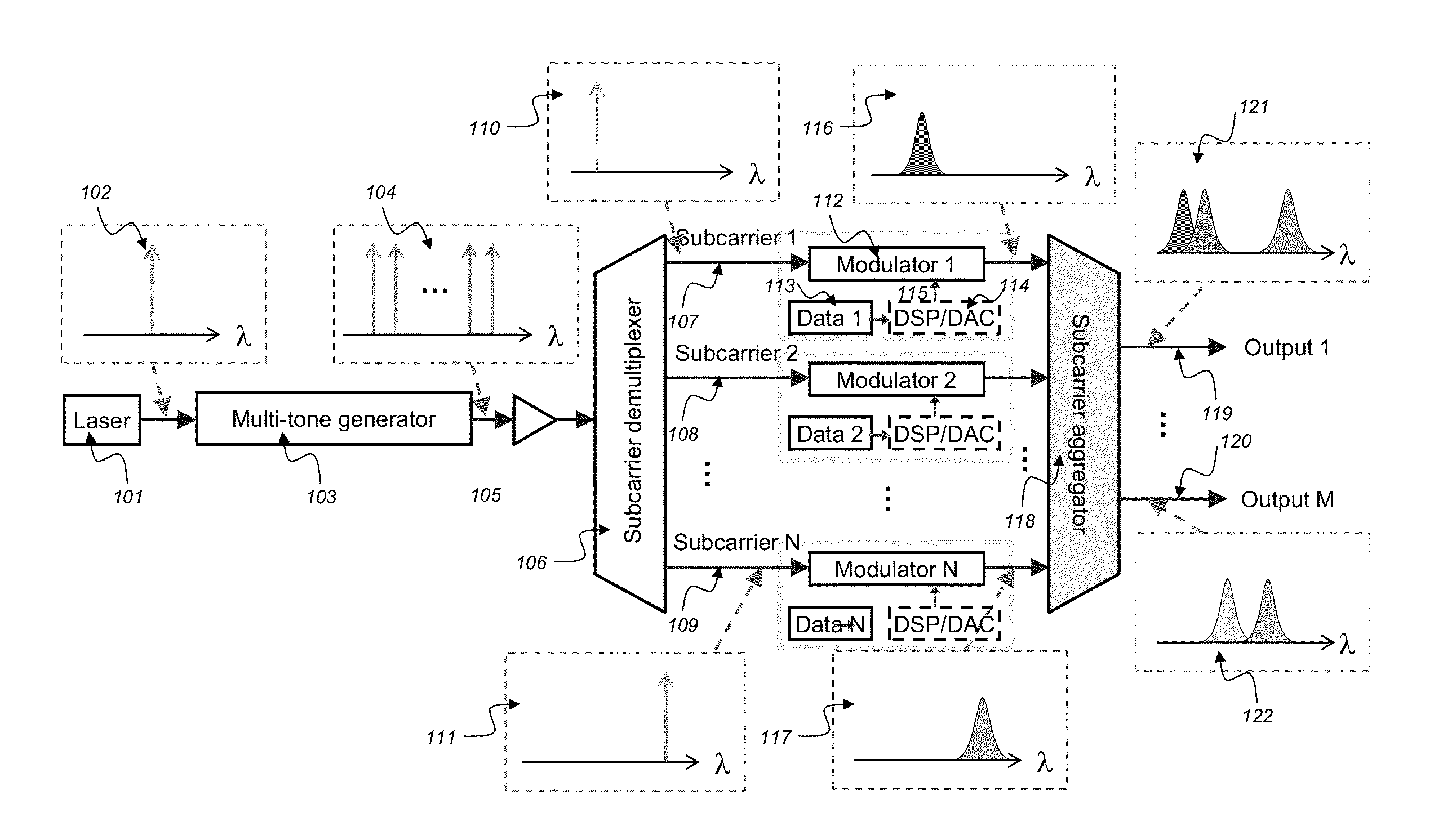
[0037]The present invention departs from the “norm” that each super-channel transceiver (and thus each WDM transponder) has only one output at the WDM side, instead we design multiple outputs for each transceiver. Different subcarriers can be directed to different outputs to go to different directions in the network. Similarly, this new super-channel transceiver (and thus the WDM transponder) can receive multiple inputs from the WDM side. As a result, the transmission direction can be selected at subcarrier granularity and not the entire super-channel granularity. With the invention, by adding this feature, the unused subcarriers can be utilized for traffic in other directions / destinations, and the switching granularity can be finer, which brings better flexibility in the network.

[0038]FIG. 5 shows the proposed multi-direction variable optical transmitter based on super-channel technology. In this illustration, super-channel transmitter with single light source is used. The front pa...


PUM


Abstract

An optical transceiver including a multi-direction variable transmitter including multiple outputs with different subcarriers being directed to different ones of the outputs to go to different directions in a network, and a multi-direction variable receiver for receiving multiple inputs thereby enabling transmission direction in a network with the transceiver at subcarrier granularity and avoiding entire super-channel granularity and enabling unused subcarriers to be utilized for traffic in other directions or destinations and making switching granularity finer for flexibility in the network.

Description

RELATED APPLICATION INFORMATION[0001]This application claims priority to provisional application No. 61 / 754,357, entitled “Multi-Direction Variable Optical Transceiver”, filed Jan. 18, 2013, the contents thereof are incorporated herein by referenceBACKGROUND OF THE INVENTION[0002]The present invention relates generally to optical networks, and more particularly, to a multi-direction variable optical transceiver.[0003]The following prior documents referenced in the background discussion, not material to patentability of the claimed invention, nevertheless provide additional information.Super-Channel Experiment:[0004][Xia1] T. J. Xia, G. A. Wellbrock, et al., “ Field Experiment with Mixed Line-Rate Transmission (112-Gb / s, 450-Gb / s, and 1.15-Tb / s) over 3,560 km of Installed Fiber Using Filterless Coherent Receiver and EDFAs Only”, Proc. OFC-NFOEC, paper PDPA3, 2011.[0005][Xia2] T. J. Xia, G. A. Wellbrock, et al., “10,000-km Enhanced Long-Haul Transmission of 1.15-Tb / s Superchannel usin...

Claims


Application Information

Patent Timeline
Patent Type & Authority Applications(United States)
IPC IPC(8): H04Q11/00
CPCH04Q11/0003H04B10/40H04B10/506H04J14/0298H04Q11/0005H04Q2011/0016
Inventor JI, PHILIP NANWANG, TINGAONO, YOSHIAKI
Owner NEC CORP
Why Eureka
Try Eureka