Smart endpoint and smart monitoring system having the same

Active Publication Date: 2009-08-27
IND TECH RES INST
View PDF6 Cites 22 Cited by
  • Summary
  • Abstract
  • Description
  • Claims
  • Application Information

AI Technical Summary

Benefits of technology

[0012]As taught above, the present invention is adapted to integrate an identification code, e.g., an RFID identification code, a digital video camera, sensors, or other personal wireless apparatuses, as well as the functions of image identification and digital signal processing. In such a way, sensors and video cameras of the video monitoring systems can be made smart, the instant image processing capability of the video monitoring system can be improved, and the application of integrating diffe

Problems solved by technology

As such, it is very hard to combine the individual technical components for the video monitoring system to achieve a complete sensibility to the ambient.
However, this increases the load of data processing at the backside servers, and delay the time of processing.
As such, the increased load and the delayed time will affect seriously the performance of a system which is configured for providing an instant (or real time) monitoring.
Further, a typical video monitoring system equipped with only a video camera exhibits a restricted behavior identification function to whom being monitored.
In other words, without being assisted by other sensing technolog

Method used


Image

  • Smart endpoint and smart monitoring system having the same
  • Smart endpoint and smart monitoring system having the same
  • Smart endpoint and smart monitoring system having the same

Examples


Example

[0018]Reference will now be made in detail to the present preferred embodiments of the invention, examples of which are illustrated in the accompanying drawings. Wherever possible, the same reference numbers are used in the drawings and the description to refer to the same or like parts.

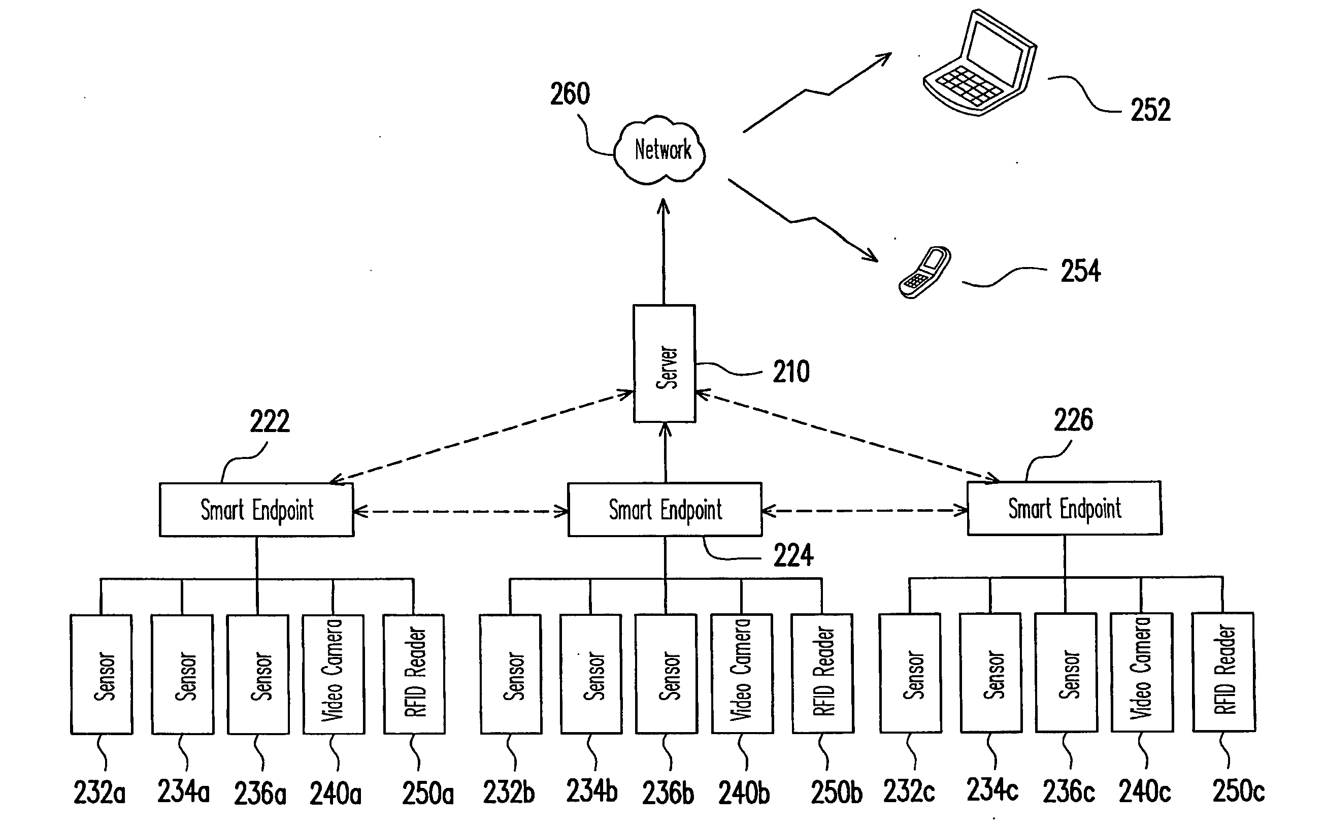
[0019]FIG. 1 is a schematic block diagram illustrating a smart endpoint according to an embodiment of the present invention. Referring to FIG. 1, the smart endpoint 100 includes a central processing unit (CPU) 110, an interface module 120, a digital signal processing (DSP) unit 130, and a memory module 140.

[0020]The CPU 110 is provided for controlling operations of other components in the entire smart endpoint 100.

[0021]The interface module 120 is coupled to the CPU 110, and configured for receiving a plurality of heterogeneous monitoring signals and an identification code. In details, the interface module 120 is provided serving as an interface for connecting with an external monitoring (sensing) ap...


PUM


Abstract

A smart endpoint and a smart monitoring system having the smart endpoint are provided. The smart endpoint includes a central processing unit (CPU), an interface module, a digital signal processing unit, and a memory module. The interface module is coupled to the CPU for receiving a plurality of heterogeneous monitoring signals and an identification code. The digital signal processing unit is coupled to the CPU for integrally considering the monitoring signals and the identification code to determine an abnormal event, and generate an abnormal event data thereby. The memory module is coupled to the CPU for recording the abnormal event data. As such, the present invention is adapted to determine an occurrence of an abnormal event, by which the passive monitoring can be upgraded to an active monitoring and analyzing, and thus achieving a smart monitoring.

Description

CROSS-REFERENCE TO RELATED APPLICATION[0001]This application claims the priority benefit of Taiwan application serial no. 97106238, filed on Feb. 22, 2008. The entirety the above-mentioned patent application is hereby incorporated by reference herein and made a part of specification.BACKGROUND OF THE INVENTION[0002]1. Field of the Invention[0003]The present invention generally relates to monitoring systems, and more particularly, to a smart endpoint and a smart monitoring system having such a smart endpoint.[0004]2. Description of Related Art[0005]Although most published so called smart video monitoring systems, e.g., IBM Smart Surveillance System (S3), have functions, such as identity tracking, location tracking, and activity tracking, and many technical components (or modules) for interpreting video data captured by video cameras by referring to historical background data. However, these functions and technical components are almost all developed individually and independently. As...

Claims


Application Information

Patent Timeline
IPC IPC(8): G06F15/173
CPCG08B25/085H04L67/125H04N7/181
Inventor HSIEH, SHYI-SHINGNIEN, CHIN-CHUNGKUO, VINCENT
Owner IND TECH RES INST
Why Eureka
Try Eureka