Method and Apparatus for Automated Multi-Drilling and Multi-Rivet Machine

a multi-rivet machine and multi-drilling technology, applied in the direction of manufacturing tools, transportation and packaging, other manufacturing equipment/tools, etc., can solve the problems of further limitations and disadvantages of conventional manufacturing approaches, and the importance of manufacturing costs

Active Publication Date: 2014-07-31
THE BOEING CO
View PDF5 Cites 25 Cited by
  • Summary
  • Abstract
  • Description
  • Claims
  • Application Information

AI Technical Summary

Benefits of technology

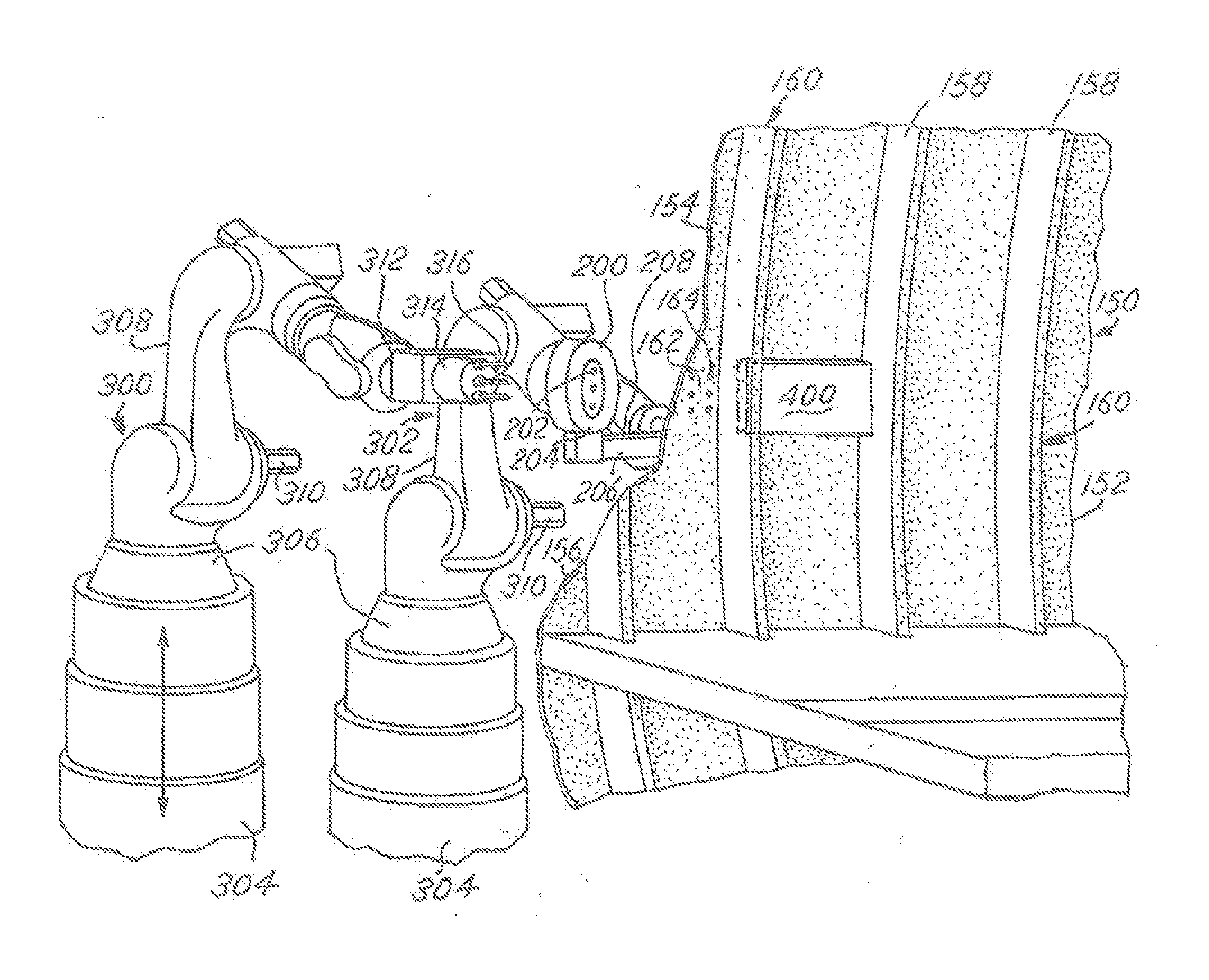
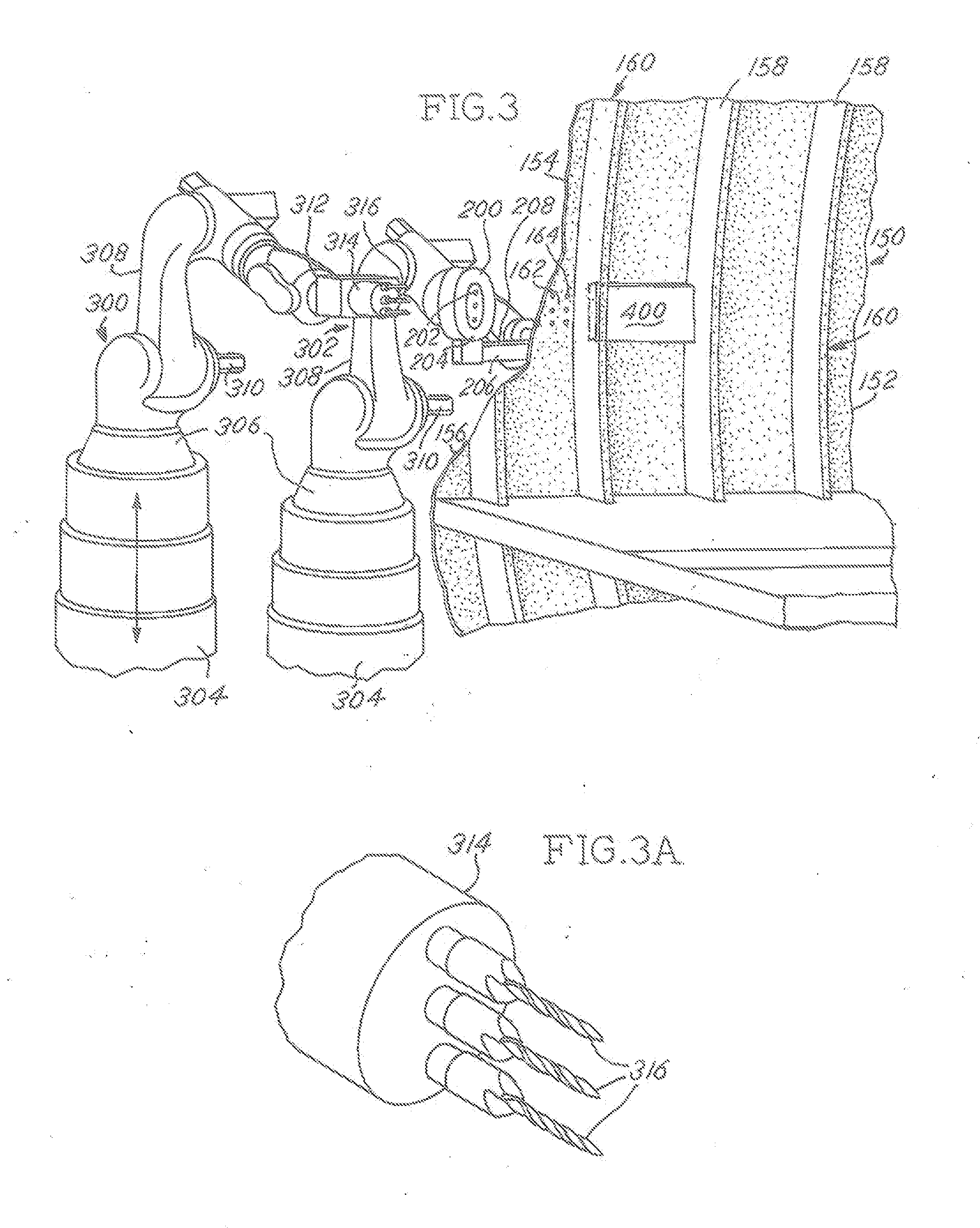
[0007]An electromagnet is placed against the exterior or outboard side of the components and a magnetically attractive backing plate member is placed against the interior or inboard side of the two components. It is important for the electromagnet to be aligned with the magnetically attractive backing plate member while both the electromagnet and magnetically attractive backing plate member are aligned with the overlapping fastener receiving zone. The electromagnet is activated for thereby being attracted to the aligned and magnetically attractive backing plate member in the interior or inboard side of the airplane fuselage for thereby substantially clamping the two components together at the overlapping fastener receiving zone.

Problems solved by technology

In any industry, including the aerospace industry, the costs of manufacture are extremely important.
Further limitations and disadvantages of conventional manufacturing approaches will become apparent to one skilled in the art through comparison of such approaches with the present disclosure as set forth in the remainder of the present application including the drawings.

Method used


Image

  • Method and Apparatus for Automated Multi-Drilling and Multi-Rivet Machine
  • Method and Apparatus for Automated Multi-Drilling and Multi-Rivet Machine
  • Method and Apparatus for Automated Multi-Drilling and Multi-Rivet Machine

Examples


Embodiment Construction

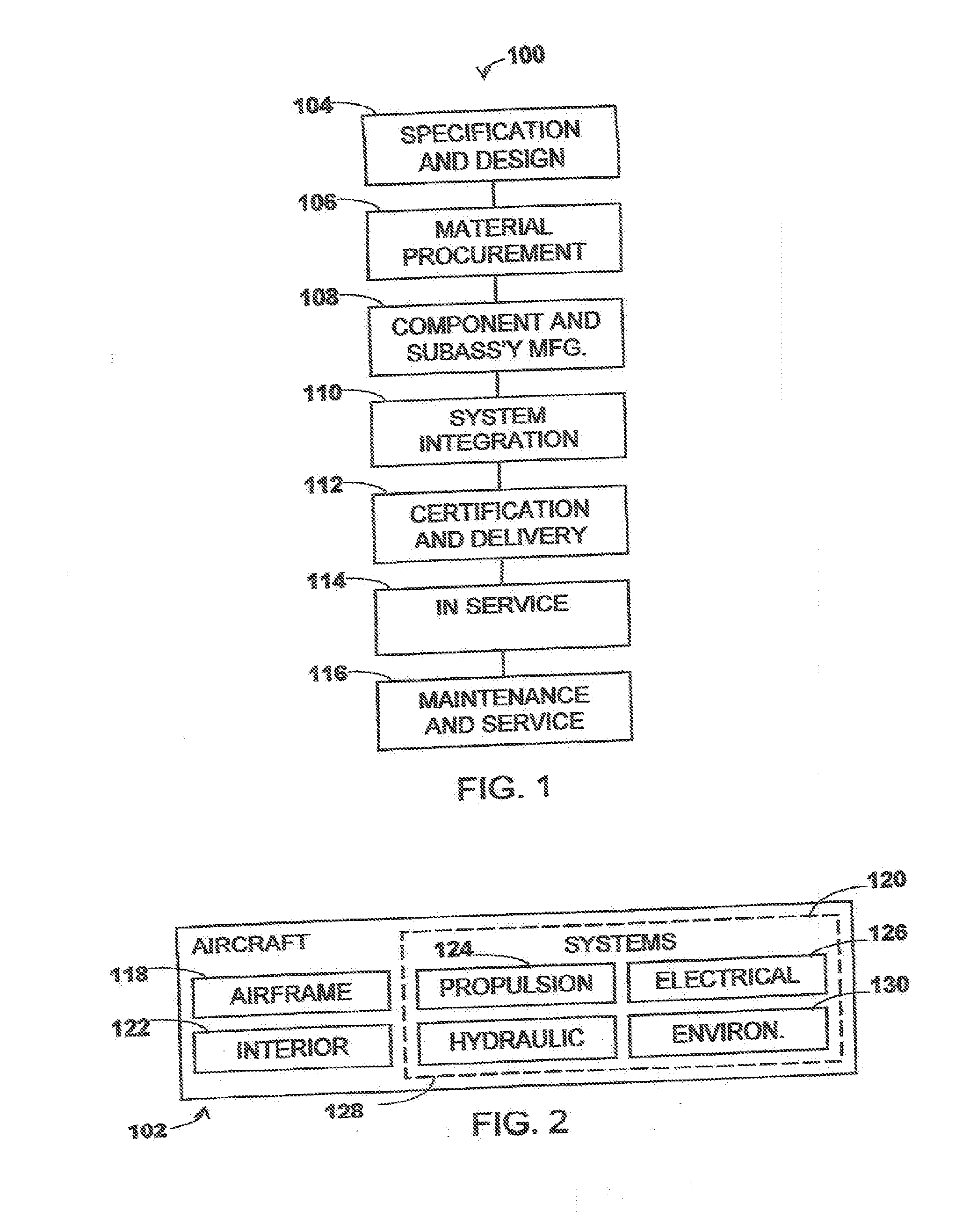
[0041]Referring more particularly to the drawings, embodiments of the disclosure may be described in the context of an airplane manufacturing and service method 100 as shown in FIG. 1 and an airplane 102 as shown in FIG. 2. During pre-production, exemplary method 100 may include specification and design 104 of the airplane 102 and material procurement 106. During production, component and subassembly manufacturing 108 and system integration 110 of the airplane 102 takes place. Thereafter, the airplane 102 may go through certification and delivery 112 in order to be placed in service 114. While in service by a customer, the airplane 102 is scheduled for routine maintenance and service 116 (which may also include modification, reconfiguration, refurbishment, and so on).

[0042]Each of the processes of method 100 may be performed or carried out by a system integrator, a third party, and / or an operator (e.g., a customer). For the purposes of this description, a system integrator may inclu...


PUM

PropertyMeasurementUnit
magnetizableaaaaaaaaaa
attractiveaaaaaaaaaa
magnetically attractiveaaaaaaaaaa

Abstract

Method and apparatus for assembling, with fasteners, components of a structure having an outboard side, an inboard side, and a supporting frame. The components are placed together on the frame. An electromagnet having a core with multiple openings is positioned on the outboard side. A magnetically attractive member is placed against the inboard side opposite and aligned with the electromagnet. When activated, the electromagnet is attracted towards the magnetically attractive member and the two hold the components together. Multiple drill members pass through the openings in the core of the electromagnet and multiple openings are drilled simultaneously through the components. Subsequently, multiple rivets or huck bolts are simultaneously inserted into the drilled openings. Finally, fasteners are hammered through the drilled openings and rivets are secured by bucking bars provided on the magnetically attractive member. Alternatively, openings are provided in the magnetically attractive member for manually securing huck bolts to the components.

Description

BACKGROUND[0001]In any industry, including the aerospace industry, the costs of manufacture are extremely important. The airplane manufacturer, like any other manufacturer of equipment, is well aware that reducing the costs of the airplane construction and assembly is important to its customers, such as airlines. Lowering costs to the airline may lower costs of travel to the passenger provided, of course, the assembly of the airplane is carried out in a very safe and efficient manner. The present disclosure is directed to accomplishing such goals.[0002]One existing manufacturing technique for assembling parts of an airplane involves the assembly of overlapping sections of the fuselage. An electromagnet is positioned on the exterior of the fuselage while a steel block is positioned on the interior of the fuselage directly opposite the electromagnet. The steel block is precisely positioned with the electromagnet by a communication system between the magnet and the block, such as a per...

Claims


Application Information

Patent Timeline
Patent Type & Authority Applications(United States)
IPC IPC(8): B23P23/04B23P19/04B64F5/00B23P11/00
CPCB23P23/04B64F5/0009B23P19/04B23P11/00B21J15/142B23B39/161B23B2215/04B23P19/069B23P2700/01B25B11/002B25B11/007B25J11/005B64F5/10Y10T29/49622Y10T29/49947Y10T29/49963Y10T29/5377Y10T29/53961
Inventor WRIGHT, RODNEY STEPHENAMIREHTESHAMI, DAVID HASSANPRINGLE, IV, JOHN W.
Owner THE BOEING CO
Why Eureka
Try Eureka