Detaching apparatus and detaching method

a technology of detaching apparatus and detaching method, which is applied in the direction of adhesives, layered products, lamination, etc., can solve the problems of inability to strictly manage the detaching speed, the detaching speed is likely to vary due to the shape change of the boundary line, and the pattern or the like are likely to be damaged

Inactive Publication Date: 2014-07-31
DAINIPPON SCREEN MTG CO LTD
View PDF10 Cites 21 Cited by
  • Summary
  • Abstract
  • Description
  • Claims
  • Application Information

AI Technical Summary

Benefits of technology

[0011]This invention was developed in view of the above problem and aims to provide a technique capable of satisfactorily detaching two plate-like bodies without damaging a pattern or the like even if the pattern or the like is carried between the two plate-like bodies in a detaching apparatus and a detaching method for detaching and separating the two plate-like bodies adhering to each other.

Problems solved by technology

If a moving speed of this boundary line, i.e. a detaching speed varies, the damage of the pattern or the like due to stress concentration is likely to occur.
Particularly, in an initial stage of the detaching process, a variation in the detaching speed due to the shape change of the boundary line is likely to occur since the shape of the boundary line is not stable.
However, with the above conventional technique, the detaching speed cannot be so strictly managed.
Particularly, there has been no way of suppressing a variation in the detaching speed due to a local shape change of the boundary line.

Method used


Image

  • Detaching apparatus and detaching method
  • Detaching apparatus and detaching method
  • Detaching apparatus and detaching method

Examples


first embodiment

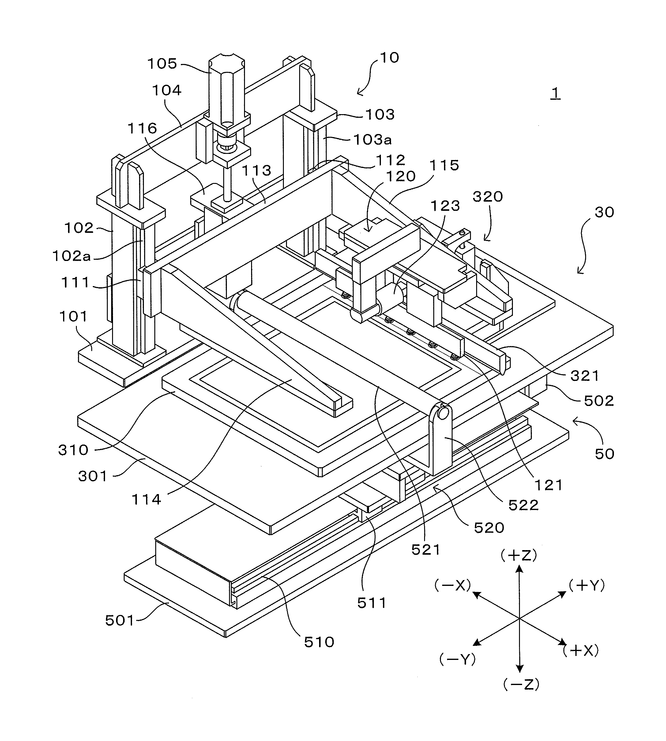
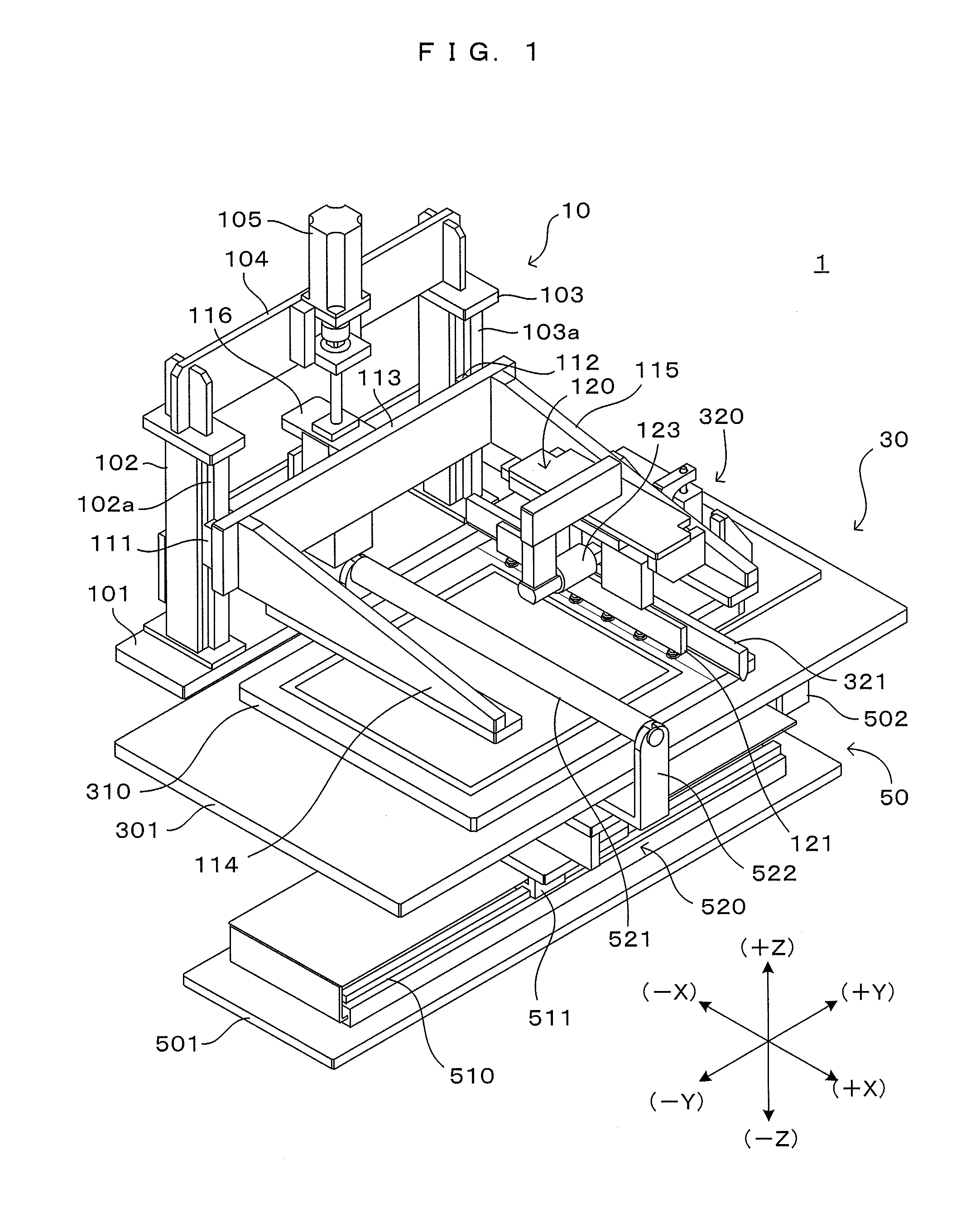
[0036]FIG. 1 is a perspective view showing a first embodiment of a detaching apparatus according to the present invention. XYZ orthogonal coordinate axes are set as shown on a right lower side of FIG. 1 to show directions in each figure in a unified manner. Here, an XY plane represents a horizontal plane and a Z axis represents a vertical axis. More specifically, a (+Z) direction represents a vertically upward direction. Note that, in each of the subsequent figures, dimensions of each component may be appropriately enlarged or reduced to facilitate the understanding of the invention. Thus, thicknesses of a substrate and a blanket to be described later and a distance between the both may be particularly shown larger than they actually are.

[0037]The detaching apparatus 1 is an apparatus for detaching two plate-like bodies loaded in a state where principle surfaces adhere to each other. For example, the apparatus 1 can be used in a part of a pattern formation process for forming a pred...

second embodiment

[0109]FIG. 9 is a perspective view showing a second embodiment of a detaching apparatus according to the present invention. In the second embodiment, XYZ orthogonal coordinate axes are set while dimensions of each component may be appropriately enlarged or reduced, similarly to the first embodiment in order to facilitate the understanding of the invention.

[0110]The detaching apparatus 2001 is, similarly to the detaching apparatus 1 (FIG. 1) of the first embodiment, an apparatus for detaching two plate-like bodies loaded in a state where principle surfaces adhere to each other. Specifically, in a pattern forming process including an applying step, a patterning step and a transferring step, this apparatus can be preferably applied for the purpose of separating a plate and a blanket or a substrate and the blanket. Of course, this apparatus may be used in applications other than this.

[0111]The detaching apparatus 2001 is so structured that a stage block 2003 and an upper suction block 2...


PUM

PropertyMeasurementUnit
angle of inclination θ1aaaaaaaaaa
taper angleaaaaaaaaaa
distanceaaaaaaaaaa

Abstract

In a detaching apparatus, a detachment starter bends one end part of a first plate-like body into a cylindrical or prismatic surface in a direction opposite to a second plate-like body, thereby forming a single and straight boundary line between an adhering region and a detached region. A separator increases a distance between a first holder holding the first plate-like body and a second holder holding the second plate-like body to separate the first and second plate-like bodies.

Description

CROSS REFERENCE TO RELATED APPLICATION[0001]The disclosure of Japanese Patent Applications enumerated below including specifications, drawings and claims is incorporated herein by reference in its entirety:[0002]No. 2013-16036 filed on Jan. 30, 2013; and[0003]No. 2013-65522 filed on Mar. 27, 2013.BACKGROUND OF THE INVENTION[0004]1. Field of the Invention[0005]The present invention relates to a detaching apparatus and a detaching method for detaching and separating two plate-like bodies adhering to each other.[0006]2. Description of the Related Art[0007]A technique for transferring a pattern or a thin film (hereinafter, referred to as “pattern or the like”) carried on a plate-like body to a substrate is known as a technique for forming a predetermined pattern or a thin film on another plate-like body such as a glass substrate or a semiconductor substrate. In this technique, after the pattern or the like is transferred from one to the other by bringing two plate-like bodies into close...

Claims


Application Information

Patent Timeline
Patent Type & Authority Applications(United States)
IPC IPC(8): B32B43/00
CPCB32B43/006Y10T156/11Y10T156/1978
Inventor KAWAGOE, MASAFUMISHOJI, KAZUHIROSHIBAFUJI, YAYOIMASUICHI, MIKIOUENO, HIROYUKIUENO, MIYOSHITANIGUCHI, KAZUTAKA
Owner DAINIPPON SCREEN MTG CO LTD
Why Eureka
Try Eureka