Plug Connection for Fluid Lines and Retaining Part for Such a Plug Connection

a technology of fluid line and plug connection, which is applied in the direction of flanged joints, sleeves/socket joints, pipes/joints/fittings, etc., can solve the problem of disadvantageous addition of locking elements

Active Publication Date: 2014-07-31
VOSS AUTOMOTIVE
View PDF5 Cites 4 Cited by
  • Summary
  • Abstract
  • Description
  • Claims
  • Application Information

AI Technical Summary

Benefits of technology

[0010]A comparable technical solution for a plug connection similar to that of the above-mentioned type has also already been proposed in the German patent application DE 10 2012 104 288.8, in which however the retaining part does not have an open, but a circumferentially closed annular contour. In this previously proposed technical solution, it can be particularly provided that one of the two collars of the retaining part is provided with a socket-like circumferentially running, preferably additionally radially inwardly curved attachment, by means of which it differs in size and shape from the other collar and by which it protrudes—seen in axial projection—with respect to the other collar. Aside from this attachment, both collars are otherwise preferably configured identically, in particular—seen in plan view—preferably congruent. While the radial expansion, which can be produced, for example, also by means of pulling or levering with a tool in the actuation area, takes place in connection with an integral deformation of the entire retaining part, only a spreading of the retaining sections with respect to each other takes place according to the invention as a result of the annular contour, so that a detachment of the retaining part from the coupling part on which it is supposed to remain can be even more securely prevented.
[0011]The distance of the actuating section to the longitudinal axis of the coupling parts or also the distance to the collars of the coupling parts, in particular to an outer edge of the collar of a coupling part configured as a plug part, can advantageously be configured smaller than was proposed by the earlier technical solution by means of the expansion mechanism of the spreading. This is important insofar as the distance of the actuating section to the collars of the coupling parts represents the actuation path for release of the connection and determines the size of the installation space of the plug connection.

Problems solved by technology

In this document, the additional locking element is considered disadvantageous.
The retaining part has necessarily an enlarged radial extension, which is considered particularly disadvantageous when only very little installation space is available.

Method used


Image

  • Plug Connection for Fluid Lines and Retaining Part for Such a Plug Connection
  • Plug Connection for Fluid Lines and Retaining Part for Such a Plug Connection
  • Plug Connection for Fluid Lines and Retaining Part for Such a Plug Connection

Examples


Embodiment Construction

[0028]It is expressly emphasized with regard to the following description that the invention is not limited to the exemplary embodiments and at the same time also not to all or several of the features of the described feature combinations, but rather each individual partial feature of each exemplary embodiment can also be of inventive importance per se and also in combination with any of the features of another exemplary embodiment separately from all other partial features described in connection therewith.

[0029]The same parts are always provided with the same reference characters in the different figures of the drawings and for this reason, as a rule, need only to be described once.

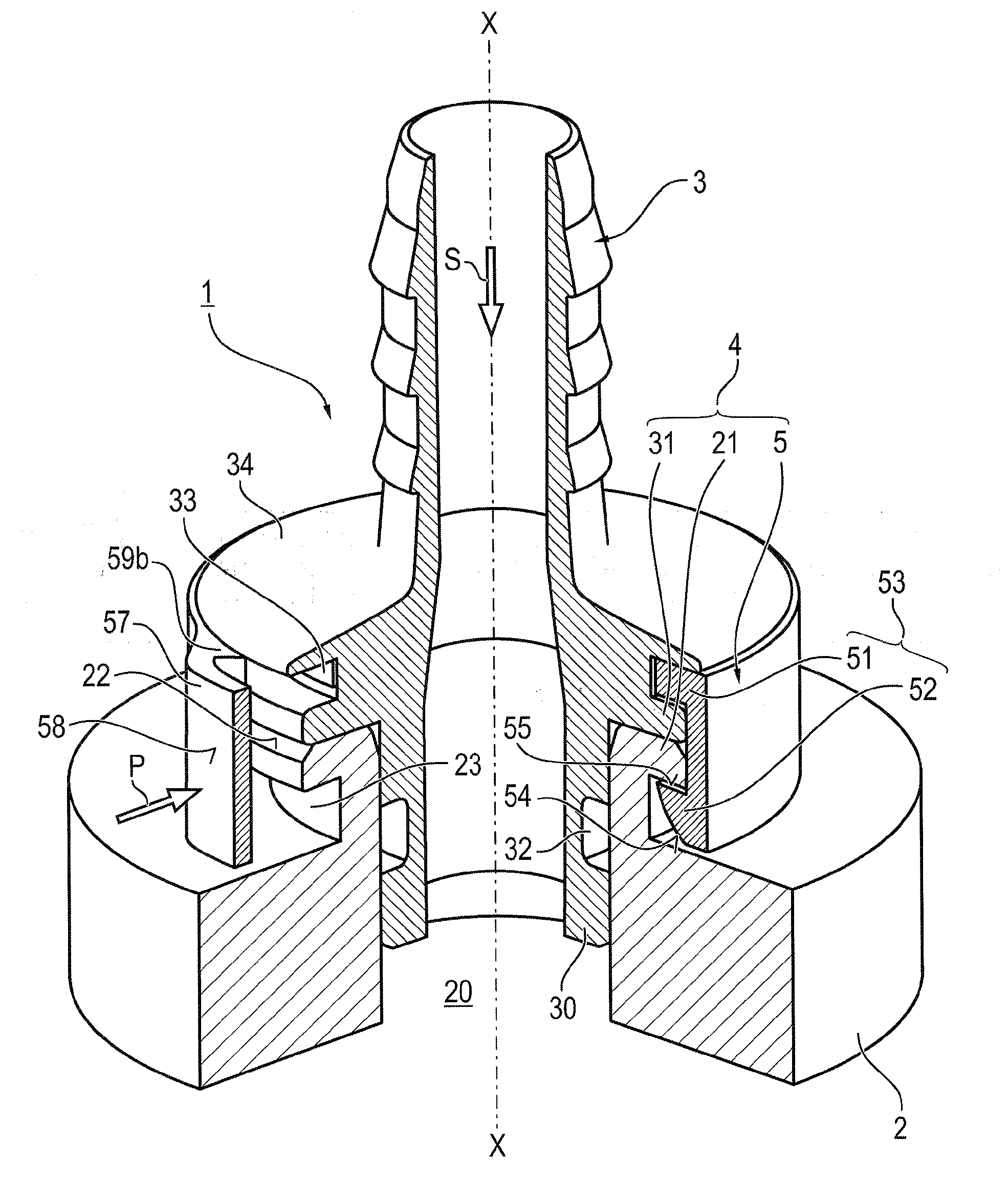
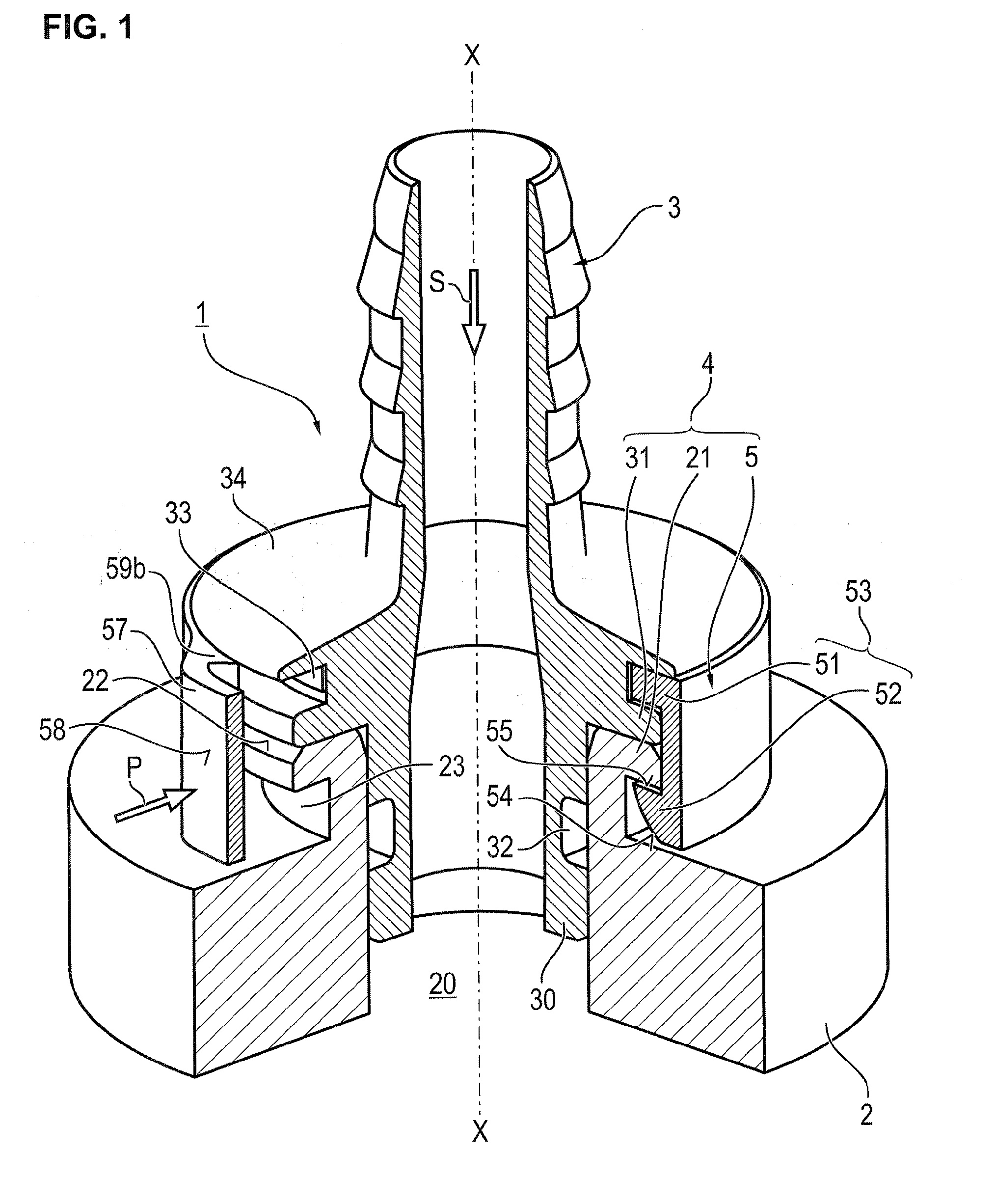
[0030]A plug connection 1 according to the invention, which can be used especially for connecting fluid lines, comprises two intermateable coupling parts 2, 3, which are inserted into each other in the assembled state represented in FIG. 1 and can be coaxially detachably locked in this state via a locki...


PUM


Abstract

A plug connection (1) for fluid lines, with two intermateable coupling parts (2, 3), which in an inserted state can be releasably locked via a locking device (4) consisting of two outer radial flange-like retaining ribs (21, 31) of the two coupling parts (2, 3), which are adjacent in an insertion direction (S) and axial (X-X) in inserted state and a retaining part (5) with an annular contour, which in preassembled state can be axially and radially fixed and undetachably assembled on one of the two coupling parts (3) and in an assembled state axially and radially encompasses the retaining ribs (21, 31) of the two coupling parts with at least one radially elastically moving retaining section (53) with a C-shaped axial section having two collars (51, 52). The plug connection incorporates features to ensure the undetachability of the retaining part (5) and minimize the space requirement, in particular during disassembly.

Description

CROSS-REFERENCE TO RELATED APPLICATIONS[0001]This application claims priority to U.S. Provisional Application Ser. No. 61 / 756,606, filed Jan. 25, 2013.FIELD OF THE INVENTION[0002]The present invention relates to a plug connection for fluid lines comprising two intermateable coupling parts, which can be releasably locked via a locking device in an inserted state, consisting, on the one hand, of two external radial flange-like retaining ribs of the two coupling parts, which are adjacent in the insertion direction when inserted, and, on the other hand, of a retaining part having an annular contour, which is axially and radially undetachably fixed on one of the two coupling parts in a preassembled state and axially and radially encompasses the retaining ribs in the assembled state with at least one radially elastically movable retaining section, which forms two collars.[0003]The present invention further relates to a retaining part for such a plug connection.BACKGROUND OF THE INVENTION[...

Claims


Application Information

Patent Timeline
Patent Type & Authority Applications(United States)
IPC IPC(8): F16L21/08
CPCF16L21/08F16L37/1225F16L23/04
Inventor HESS, JOCHEM-ANDREASSIEPER, GUNTERPLIETSCH, REINHARDZENSES, FRANK
Owner VOSS AUTOMOTIVE
Why Eureka
Try Eureka