Object distance determination from image

a distance determination and object technology, applied in image enhancement, instruments, television systems, etc., can solve the problems of unreliable depth data, complex, mathematically irreversible defocus blur, etc., to reduce or eliminate the probability of ghost images, improve and/or facilitate distance determination, reduce the complexity of both processing and hardware implementation

Active Publication Date: 2014-07-31
KONINKLIJKE PHILIPS ELECTRONICS NV
View PDF24 Cites 18 Cited by
  • Summary
  • Abstract
  • Description
  • Claims
  • Application Information

AI Technical Summary

Benefits of technology

[0009]The invention may provide improved and / or facilitated distance determination to an object based on an image from an image capture device. The distance to the object can be determined from a single image.
[0047]This may provide an improved and / or facilitated distance determination in many embodiments. In particular, it may facilitate determination of displacements between image objects in case these are overlapping. In many embodiments, the apparatus may be arranged to determine whether the image objects are overlapping and to apply the interference based displacement determination (only) if they are overlapping.

Problems solved by technology

However, conventional lens apertures introduce defocus blur which is mathematically irreversible and not very discriminative to depth.
Accordingly such approaches tend to be complex and result in relatively unreliable depth data.
However, the approach results in a system with high complexity requiring a high computational resource.
Furthermore, the approach may result in depth measurements that are less reliable and accurate than desired.
Indeed, the method is particularly difficult in the presence of depth contrasts for objects with similar intensities.

Method used


Image

  • Object distance determination from image
  • Object distance determination from image
  • Object distance determination from image

Examples


Embodiment Construction

[0069]The following description focuses on embodiments of the invention applicable to a system for determining a distance to a human being and in particular to determination of a distance to the eyes of a human from a bright pupil image. However, it will be appreciated that the invention is not limited to this application but may be applied to determination of a distance to many other objects based on many different optical characteristics.

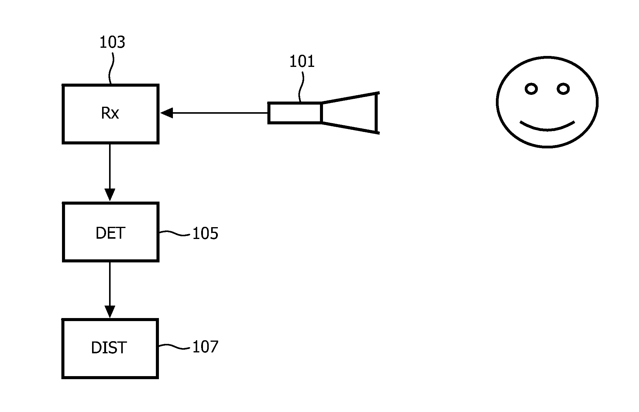
[0070]FIG. 1 illustrates an example of a system for determining a distance to an object from a single captured image.

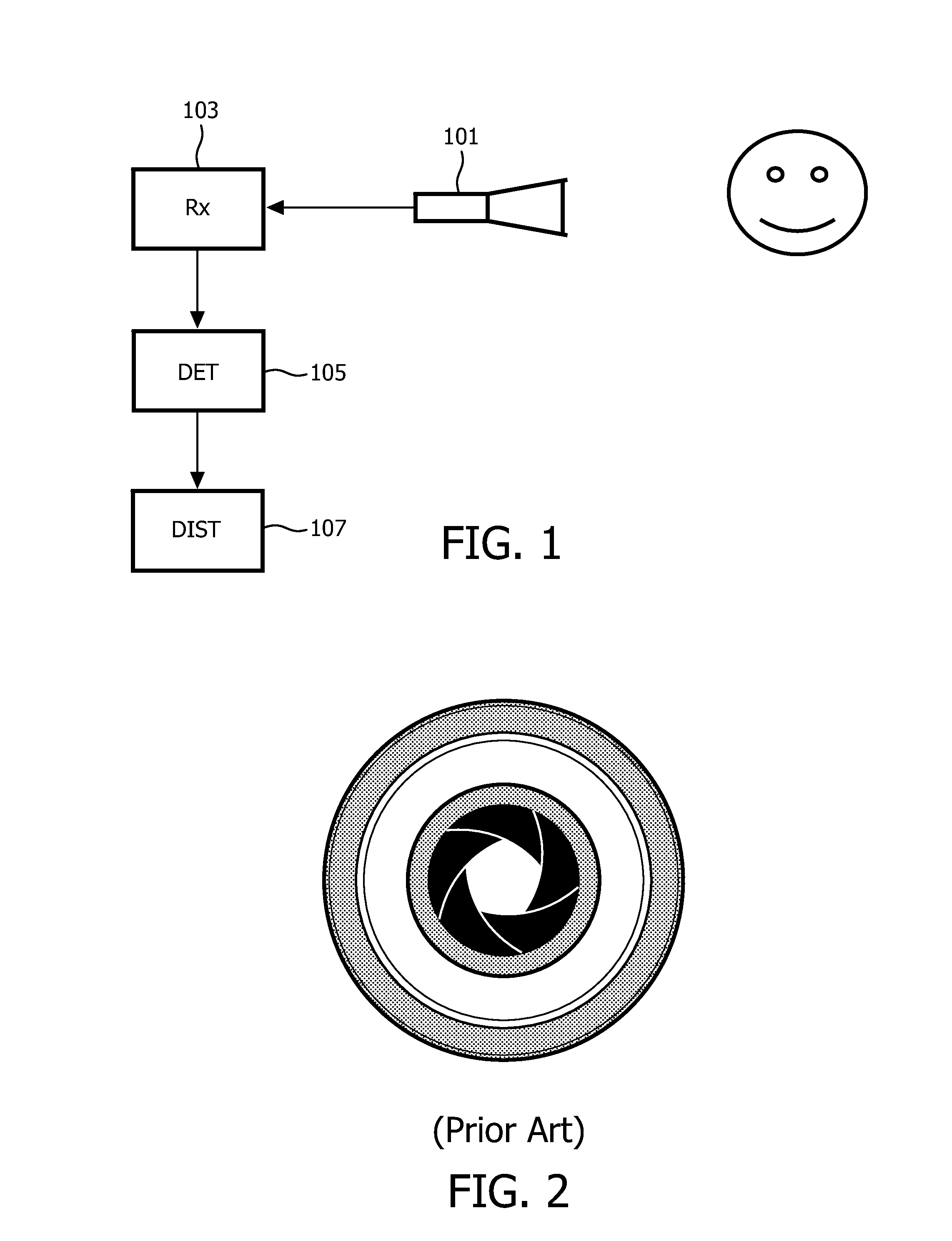
[0071]An image capture device 101 is arranged to capture an image of a scene in which the object is present. The image capture device 101 comprises a coded aperture which provides a mask for the incident light on the image sensor of the image. Further, the image sensor is positioned out of the focus plane such that the coded aperture provides a blurring of the captured image. A coded aperture is an aperture which comprises a plurali...


PUM


Abstract

A system for determining a distance to an object comprises an image capture device (101) which has a coded aperture and an image sensor which is positioned out of a focus plane of the coded aperture. A receiver (103) receives an image of a scene from the image sensor and a detector (105) detects at least two image objects of the image corresponding to ghost images of the object resulting from different openings of the coded aperture in response to an optical characteristic of the object. A distance estimator (107) then determines a distance to the object in response to a displacement in the image of the at least two image objects. The distance may be to a person and the image may be a bright pupil image wherein pupils are enhanced by reflection of light by the retina. The image may be compensated by a dark pupil image of the scene.

Description

FIELD OF THE INVENTION[0001]The invention relates to determination of a distance to an object based on a single image, and in particular, but not exclusively to determination of a distance to a person based on a bright pupil image.BACKGROUND OF THE INVENTION[0002]Determination of distance to objects based on images captured by an image capture device such as a still or moving image camera has become of increasing importance.[0003]For example, with the advent of autonomous systems capable of adapting functionality and characteristics to their environment, information about the presence of humans and their precise location is often highly desirable. Examples include monitoring systems for elderly or hospital wards, adaptive lighting systems capable of dimming locally to save energy or change beam shapes and spectral signatures to increase comfort. The precise position of human eyes, in particular, can be of interest for display purposes where the view provided is adapted to the detect...

Claims


Application Information

Patent Timeline
Patent Type & Authority Applications(United States)
IPC IPC(8): G06T7/00H04N13/04
CPCG06T2200/21G06T2207/30041G06T2207/30196G06T2207/10141G06T7/0069G06T7/004H04N13/0475G06T7/70G06T7/571H04N13/373
Inventor MUIJS, REMCO THEODORUS JOHANNESDE BRUIJN, FREDERIK JANGRITTI, TOMMASO
Owner KONINKLIJKE PHILIPS ELECTRONICS NV
Why Eureka
Try Eureka