Methods and systems for operating a bi-directional micro inverter

a micro inverter and bi-directional technology, applied in the direction of electric variable regulation, process and machine control, instruments, etc., can solve the problems of reducing the efficiency of the micro inverter, bulky and less reliable, and the use of electrolytic capacitors

Inactive Publication Date: 2014-07-31
GENERAL ELECTRIC CO
View PDF8 Cites 32 Cited by
  • Summary
  • Abstract
  • Description
  • Claims
  • Application Information

AI Technical Summary

Problems solved by technology

However, such device needs a high input ripple current from an input capacitor, resulting in the use of electrolytic capacitors, which may be bulky and le

Method used


Image

  • Methods and systems for operating a bi-directional micro inverter
  • Methods and systems for operating a bi-directional micro inverter
  • Methods and systems for operating a bi-directional micro inverter

Examples


Embodiment Construction

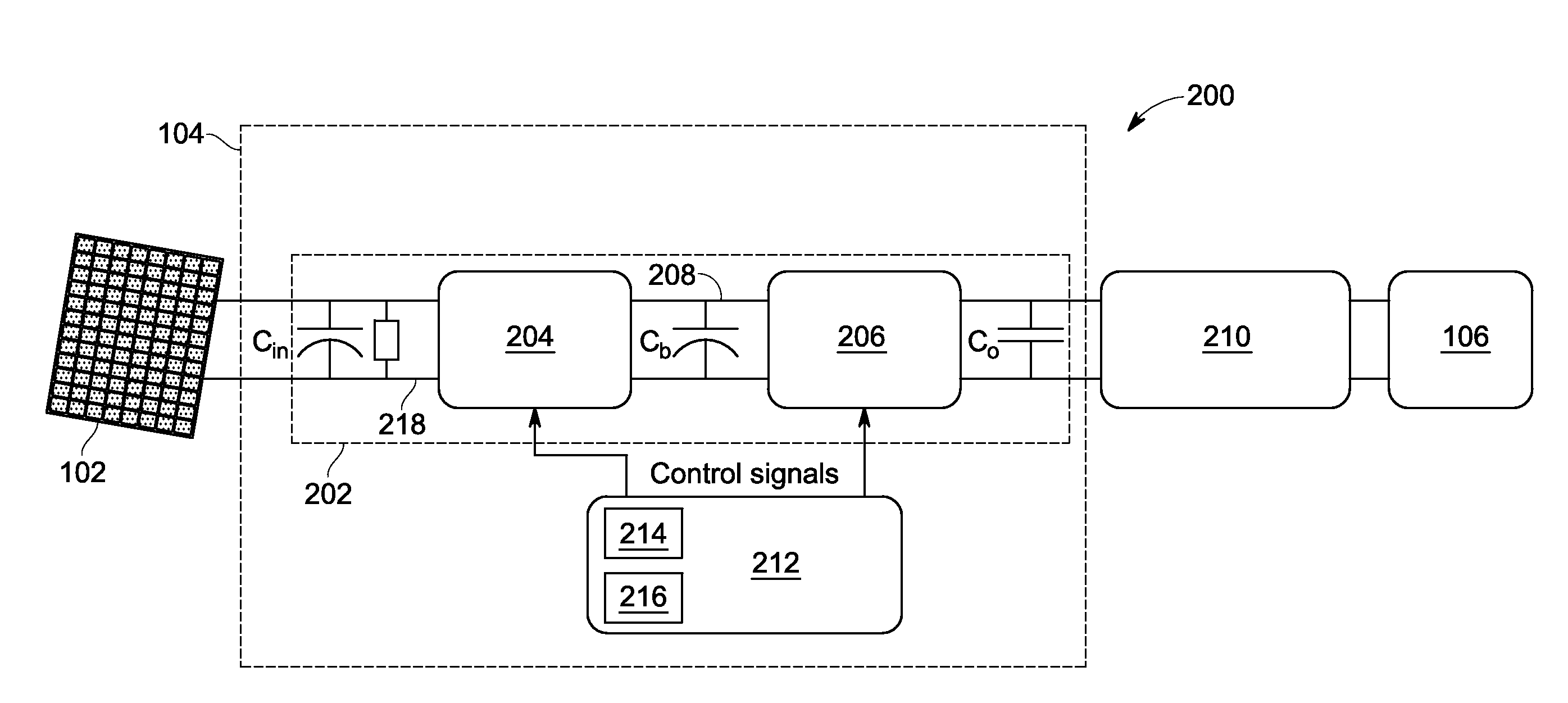
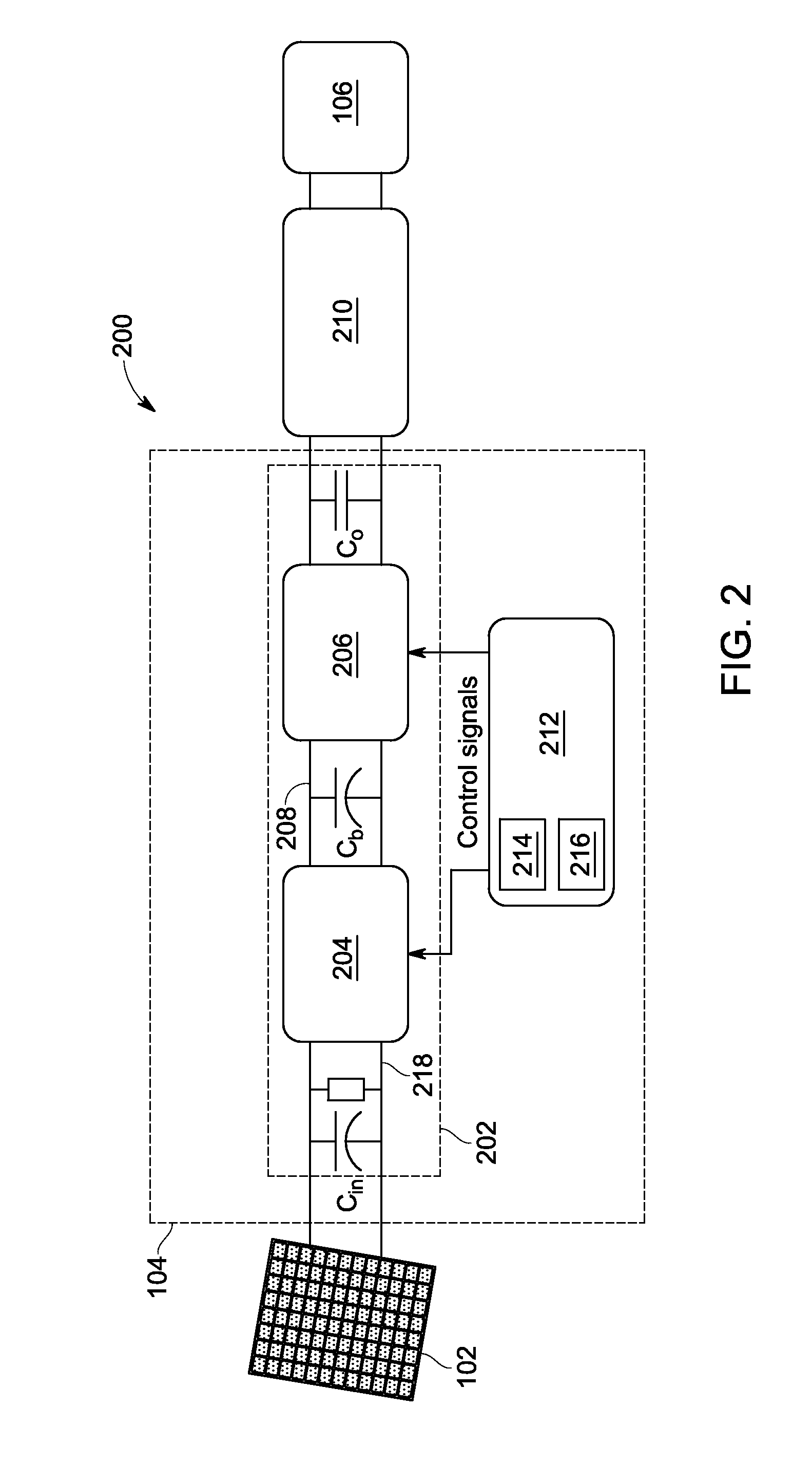
[0016]The methods and systems described herein provide a photovoltaic (PV) micro inverter that has active and reactive power generation capabilities. More specifically, the methods and systems described herein enable operation of a synchronous bi-directional power converter in four quadrant modes to achieve bi-directional power flow. The power converter operates in a forward conduction mode when PV power is available and in a reverse conduction mode or reactive power compensation mode when PV power is unavailable. A boost converter reduces ripple voltage within the power converter, eliminating a need for electrolytic capacitors, which improves reliability. Peak and RMS currents flowing through a transformer of the power converter are reduced, enabling a transformer smaller in size to be used. Additionally, synchronous switches are utilized in the power converter, resulting in improved efficiency of the micro inverter.

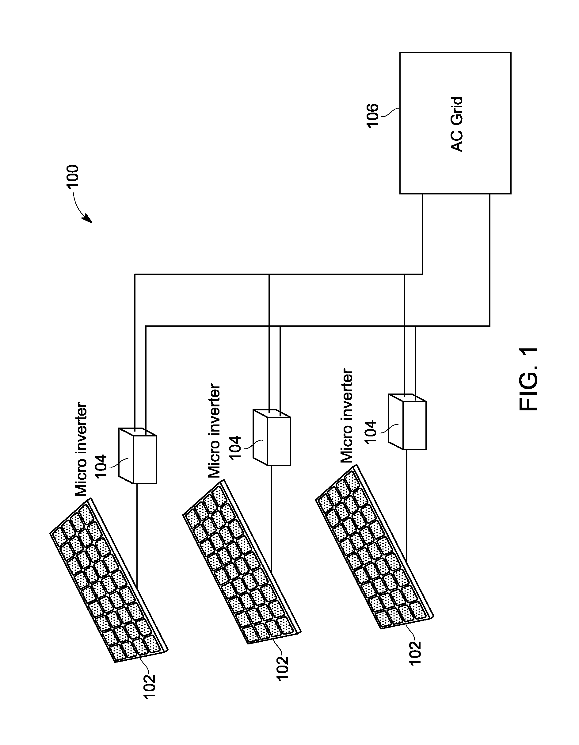
[0017]FIG. 1 is a schematic diagram of an exemplary power distribu...


PUM


Abstract

A micro inverter includes a synchronous bi-directional power converter and a controller communicatively coupled to the synchronous bi-directional power converter. The controller is configured to operate the micro inverter in a forward conduction mode when photovoltaic (PV) power is available and operate the micro inverter in at least one of a reverse conduction mode and a reactive power compensation mode when PV power is unavailable.

Description

BACKGROUND[0001]The present application relates generally to operating a micro inverter, and more specifically, to a synchronous bi-directional power converter for use in a micro inverter.[0002]Sun is a potential source of renewable energy that is becoming increasingly attractive as an alternative source of energy. Solar energy in the form of irradiance may be converted to electrical energy using solar cells. A more general term for devices that convert light to electrical energy is “photovoltaic cells.” The electrical energy output of a photovoltaic (“PV”) cell is in the form of direct current (“DC”). In order for this DC output to be utilized by at least some conventional alternating current (“AC”) electronic devices, as well as the electric power grid, it must first be converted from DC to AC. Conventionally, this DC to AC conversion is performed with a power converter.[0003]One type of solar power converter, a micro inverter, converts DC electricity from a single solar panel to ...

Claims


Application Information

Patent Timeline
IPC IPC(8): H02M7/797G05F1/70
CPCG05F1/70H02M7/797H02J3/1835H02M7/4807Y02E40/30H02J2300/24H02J3/381Y02E10/56H02J2300/26H02J3/388
Inventor KANDASAMY, JEYAPRAKASHKEERAMTHODE, REMESH KUMARSRIGHAKOLLAPU, NVS KUMAR
Owner GENERAL ELECTRIC CO
Why Eureka
Try Eureka