Robot and robot controller

a robot controller and robot technology, applied in the field of robot and robot controller, can solve the problems of poor work efficiency and the inability to anticipate vibration suppression, and achieve the effect of reducing the number of vibrations and improving the work efficiency

Active Publication Date: 2014-07-31
SEIKO EPSON CORP
View PDF26 Cites 20 Cited by
  • Summary
  • Abstract
  • Description
  • Claims
  • Application Information

AI Technical Summary

Benefits of technology

[0007]An advantage of some aspects of the invention is to provide a robot and a robot controller that may operate as a high-speed-specialized type, a vibration-suppression-specialized type at deactivation, and a compatible typ...

Problems solved by technology

Accordingly, there has been a problem of poor work efficiency.
Further, the anticipated vibration su...

Method used


Image

  • Robot and robot controller
  • Robot and robot controller
  • Robot and robot controller

Examples


first embodiment

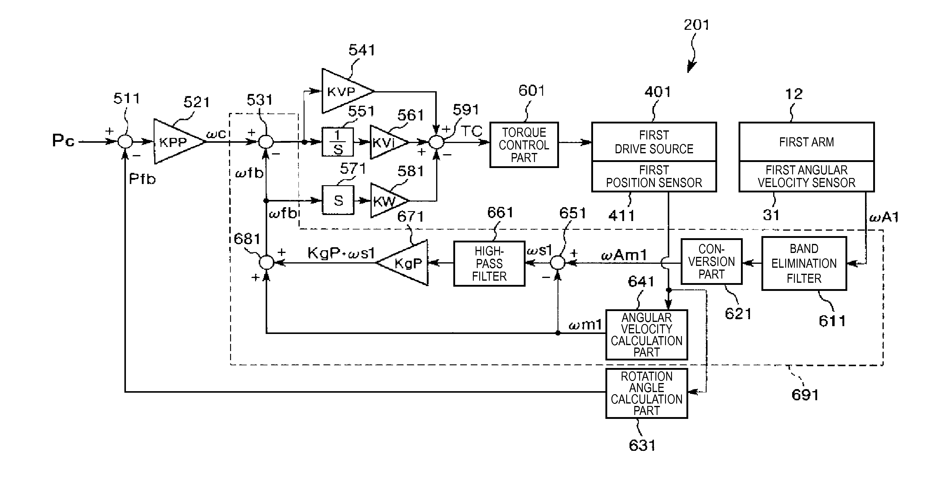
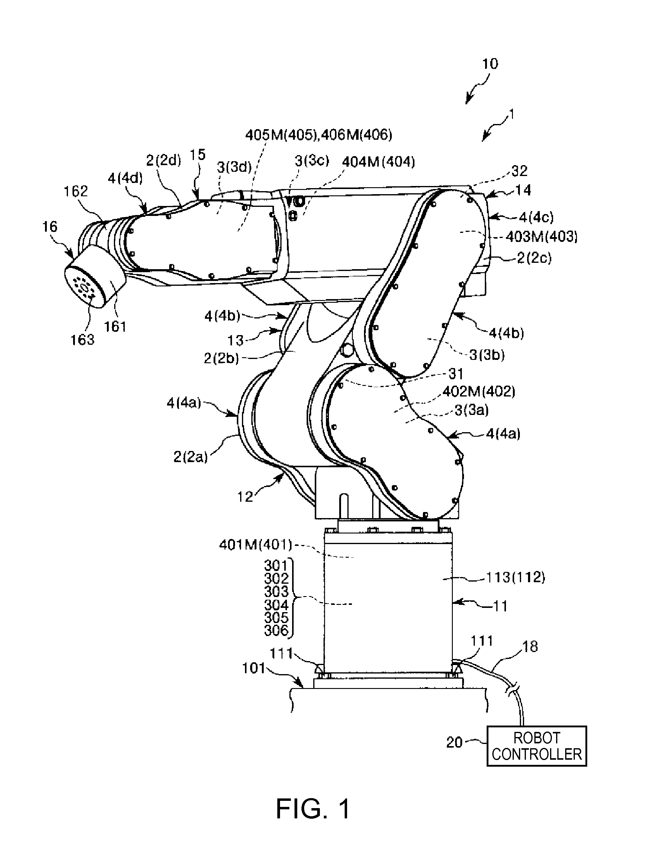
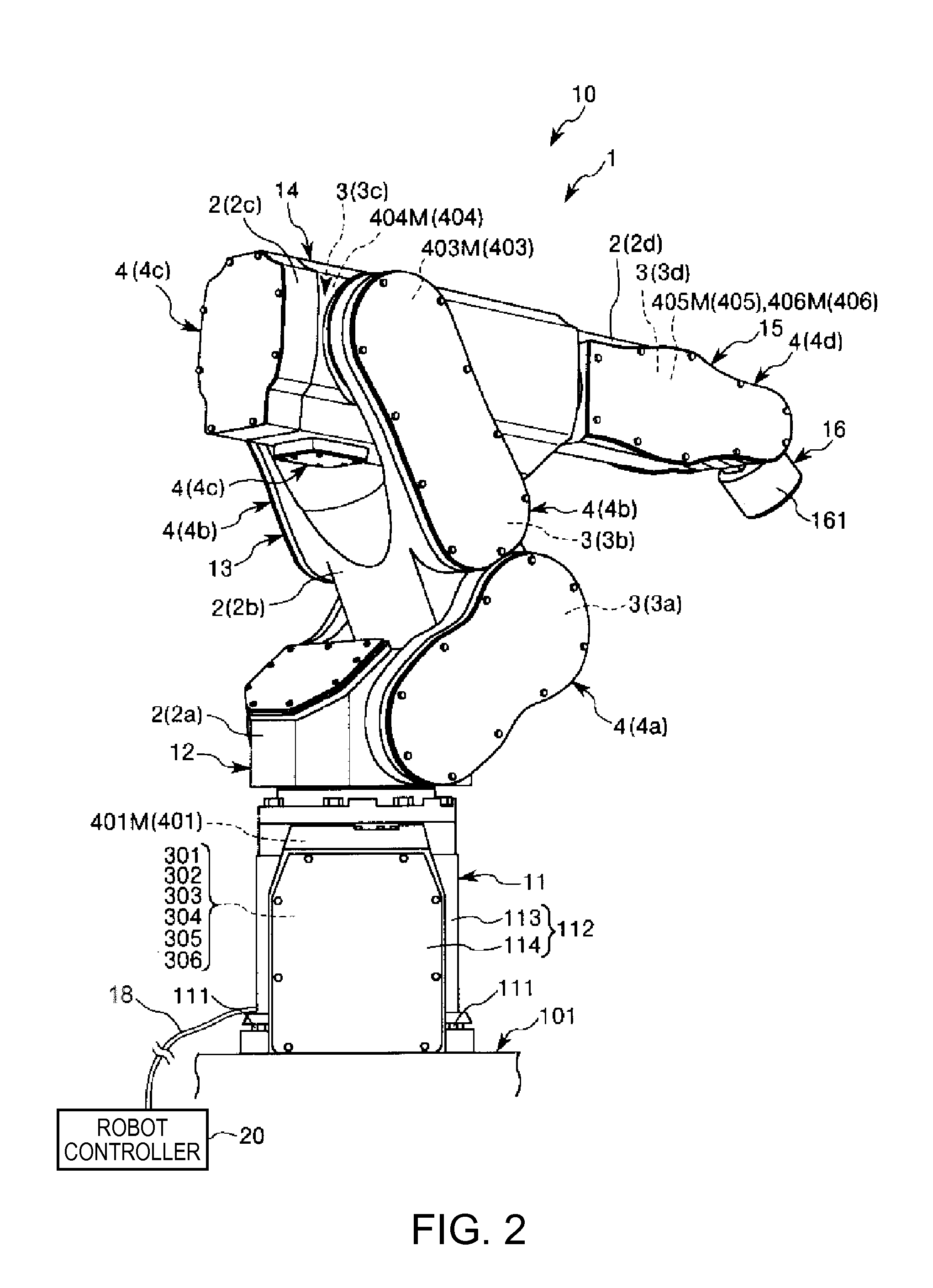
[0052]FIG. 1 is a perspective view of a robot of the first embodiment of the invention as seen from the front side. FIG. 2 is a perspective view of the robot shown in FIG. 1 as seen from the rear side. FIG. 3 is a schematic diagram of the robot shown in FIG. 1. FIG. 4 is a schematic diagram of the robot shown in FIG. 1. FIG. 5 is a block diagram of a part of robot shown in FIG. 1. FIG. 6 is a block diagram of the part of robot shown in FIG. 1. FIG. 7 is a diagram for explanation of a cycle time. FIG. 8 is a diagram for explanation of an excessive amount of passage from position. FIGS. 9 to 14 are respectively block diagrams of the part of robot shown in FIG. 1.

[0053]Note that for convenience of explanation, the upside in FIGS. 1 to 4 is referred to as “upper” or “above” and the downside is referred to as “lower” or “below”. Further, the base side in FIGS. 1 to 4 is referred to as “proximal end” and the opposite side is referred to as “distal end”. Furthermore, in FIGS. 1 and 2, a ro...

second embodiment

[0188]FIG. 15 is a schematic diagram showing a robot of the second embodiment of the invention. FIG. 16 is a schematic diagram of the robot shown in FIG. 15.

[0189]In the following, the explanation of the second embodiment will be centered on the difference from the above described first embodiment and the explanation of the same items will be omitted.

[0190]Note that for convenience of explanation, the upside in FIG. 15 is referred to as “upper” or “above” and the downside is referred to as “lower” or “below”. Further, the base side in FIGS. 15 and 16 is referred to as “proximal end” and the opposite side is referred to as “distal end”. Furthermore, in FIGS. 15 and 16, a robot controller 20 is shown by block diagrams, respectively. Further, in FIGS. 15 and 16, an inertia sensor 33 is shown outside of the arm 12 for making its existence clear.

[0191]A robot 1A of the second embodiment shown in FIGS. 15 and 16 is called a scalar robot.

[0192]A robot main body 10A of the robot 1A includes...


PUM


Abstract

A robot has an operation mode setting unit that sets an operation mode of the robot. The operation mode setting unit changes a correction factor multiplied by the maximum acceleration and the maximum deceleration of an arm and the servo gain of a servo circuit, and thereby selectively sets the operation mode to one of a first operation mode, a second operation mode in which the arm operates faster than in the first operation mode, and a third operation mode in which the arm vibrates less than in the first operation mode.

Description

BACKGROUND[0001]1. Technical Field[0002]The present invention relates to a robot and a robot controller.[0003]2. Related Art[0004]Robots having rotatable arms and working with freedom in three-dimensional spaces have been known. There has been a demand for such robots to operate in industrial settings at a high speed with improved work efficiency during routine operations and, on the other hand, to have suppressed vibrations during performance of delicate work (precise work) so the robot can perform precisely.[0005]Accordingly, robots that may select a standard mode in which the robot operates at a standard speed and a fast mode in which the robot operates at a high speed as operation modes of the robot have been proposed (for example, see Patent JP-A-4-286003. Note that, when the mode is changed between the standard mode and the fast mode, the servo gain of a servo circuit controlling the operation of the robot is changed.[0006]However, in robots of the related art, it is necessary...

Claims


Application Information

Patent Timeline
IPC IPC(8): B25J9/16
CPCB25J9/1651B25J9/1641B25J9/1638B25J9/1646G05B19/19G05B19/404G05B2219/42114
Inventor TOSHIMITSU, SHUNSUKEFUJIMORI, HIROAKIIGARASHI, KATSUJIONO, MASATOSHIASADA, ATSUSHI
Owner SEIKO EPSON CORP
Why Eureka
Try Eureka