Cordless retractable roller shade for window coverings

a retractable roller and window covering technology, applied in the direction of shutters/movable grilles, door/window protective devices, wing arrangements, etc., can solve the problems of increasing force, affecting the use of the window covering, so as to reduce the bias of the spring, reduce the rotational bias or force applied, and relieve the effect of tension and bias

Active Publication Date: 2014-08-07
HUNTER DOUGLAS INC
View PDF11 Cites 66 Cited by
  • Summary
  • Abstract
  • Description
  • Claims
  • Application Information

AI Technical Summary

Benefits of technology

[0014]In one example of the operating system, the biasing component is a spring motor in the form of a coil spring positioned inside the roller to extend along a portion of the roller's length. One end of the coil spring is operably connected to the roller at a fixed location for unitary rotation therewith. An opposite end of the coil is movably connected to the roller for unitary rotation with the roller and reversible translation along the length of the roller. The movable end of the coil spring is driven or moved by a drive system or drive mechanism that includes a longitudinally extending threaded shaft fixed to the head rail so that the roller can rotate thereabout. A nut connected to the movable end of the coil spring is operably mounted on the threaded shaft for reversibly translatable movement along the length of the threaded shaft upon rotation of the roller. As the roller rotates, the nut moves along the threaded length of the shaft and also along the length of the roller. Movement of the nut along the shaft causes the coil spring to extend (placing tension and bias in the spring) or retract (relieving such tension and bias) depending upon the direction of movement of the nut. The spring generally retains a degree of extension, even with the shade in the fully retracted position, so as to at least slightly bias the bottom rail, through the operating system, upwardly toward the head rail. Movement of the bottom rail downwardly away from the head rail causes the roller to rotate, which thereby causes the nut to extend the spring and increase the rotational bias or force applied to the roller. Movement of the bottom rail upwardly toward the head rail causes the nut to move toward the fixed end of the coil spring to reduce the bias of the spring.
[0015]The coil spring thereby assists an operator in raising the bottom rail. A predetermined amount of friction is built into the system via the inter-relationship of the nut to the threaded shaft so as to help retain the bottom rail at any displaced relationship from the head rail. The amount of built-in friction is determined by the variable operative strength of the spring at various displacements of the bottom rail from the head rail.
[0019]Additionally to this first example, the cordless retractable shade includes a non-rotatable element operably associated with the roller, wherein the biasing component further comprises a spring operably connected between the roller and the non-rotatable element. Rotation of the roller in a first direction increases a biasing force exerted by the spring on the roller, and rotation of the roller in a second direction decreases the biasing force exerted by the spring on the roller.

Problems solved by technology

Operating and pull cords can be an issue with retractable coverings, as in some instances the cords may become tangled and difficult to use, fray or break, damage the covering from repeated wear, and may sometimes form loops that may present a risk to users.
The force increases with the extension of the shade because the bias element in the operating system develops an increasing load as the shade extends.

Method used


Image

  • Cordless retractable roller shade for window coverings
  • Cordless retractable roller shade for window coverings
  • Cordless retractable roller shade for window coverings

Examples


Embodiment Construction

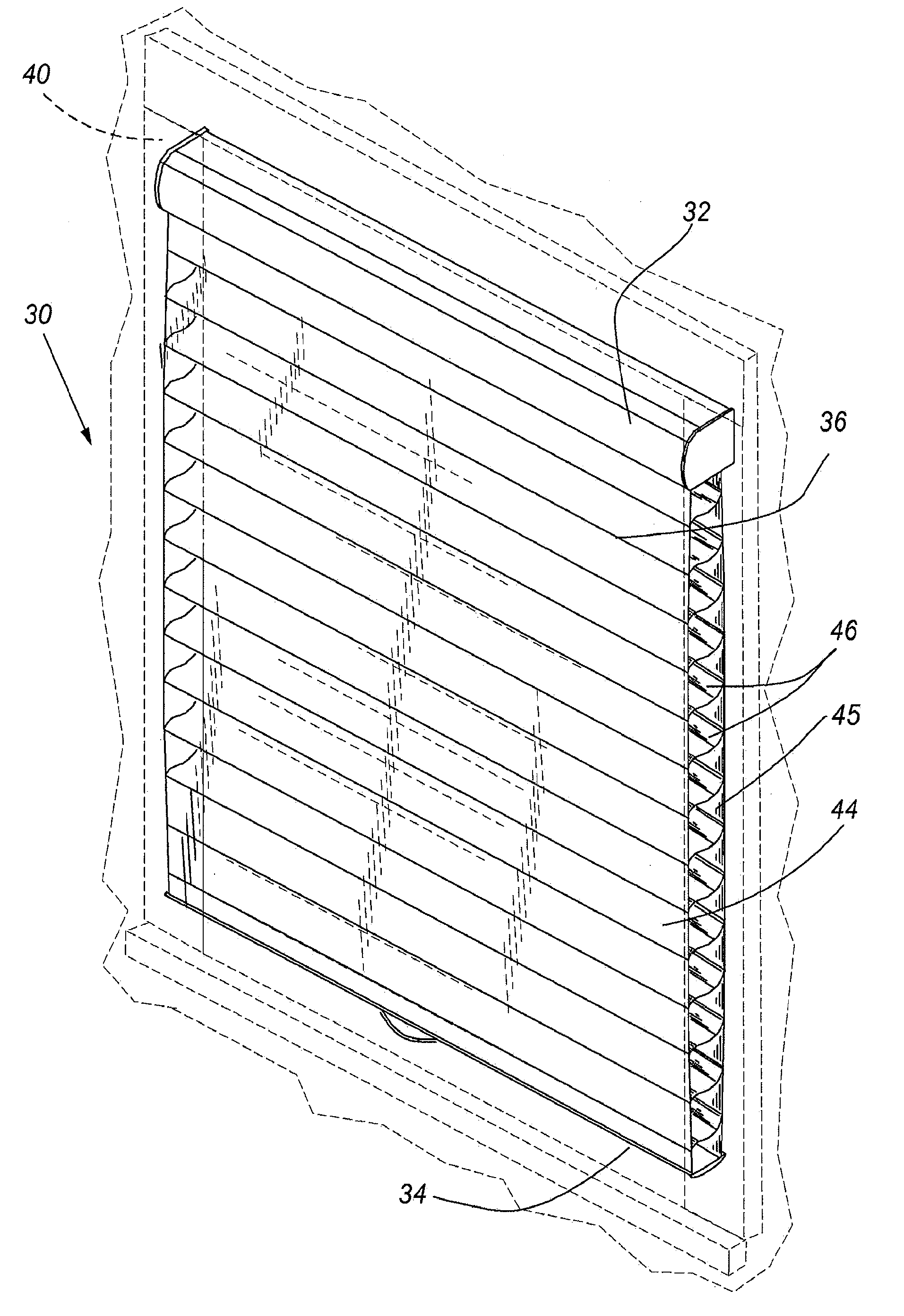
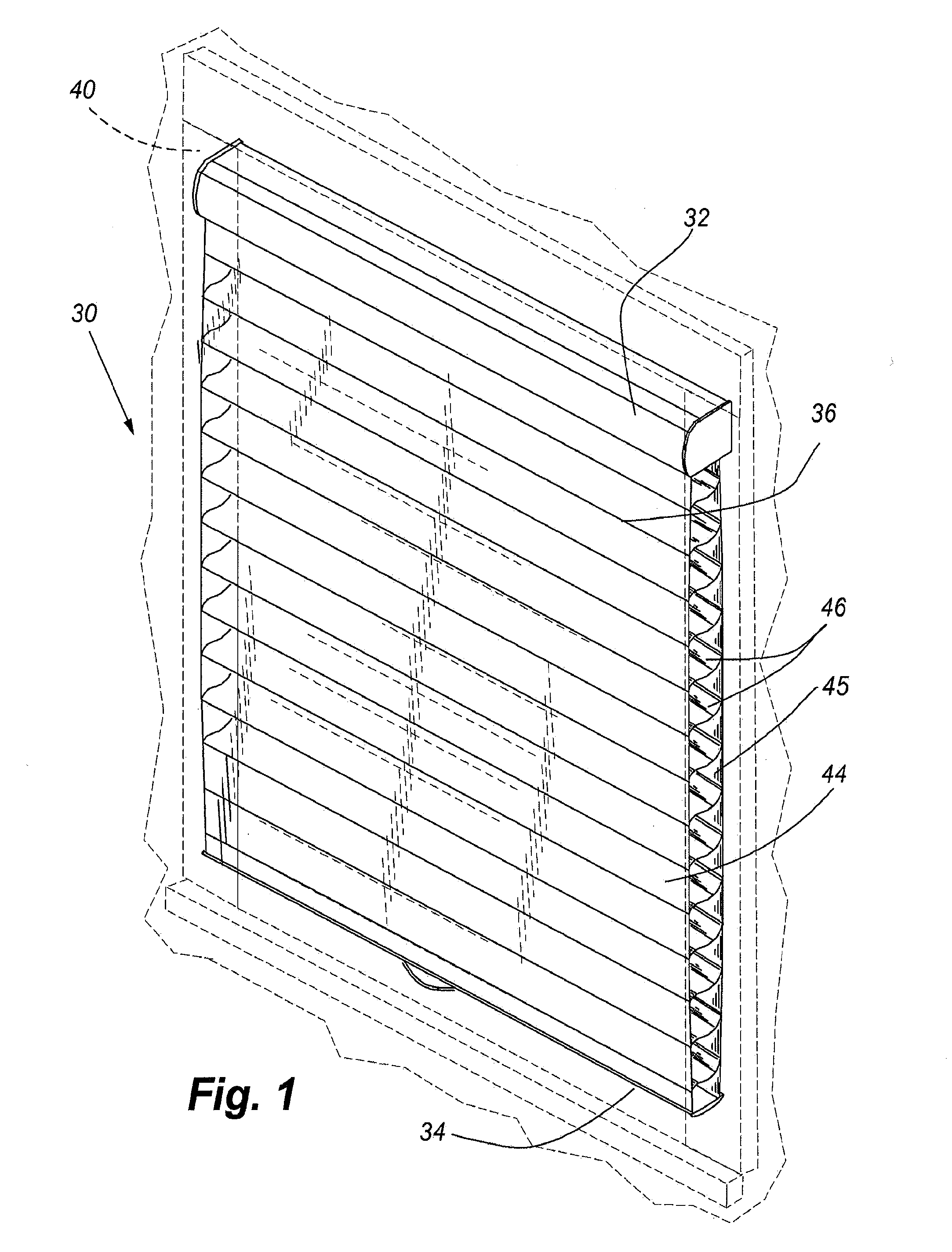
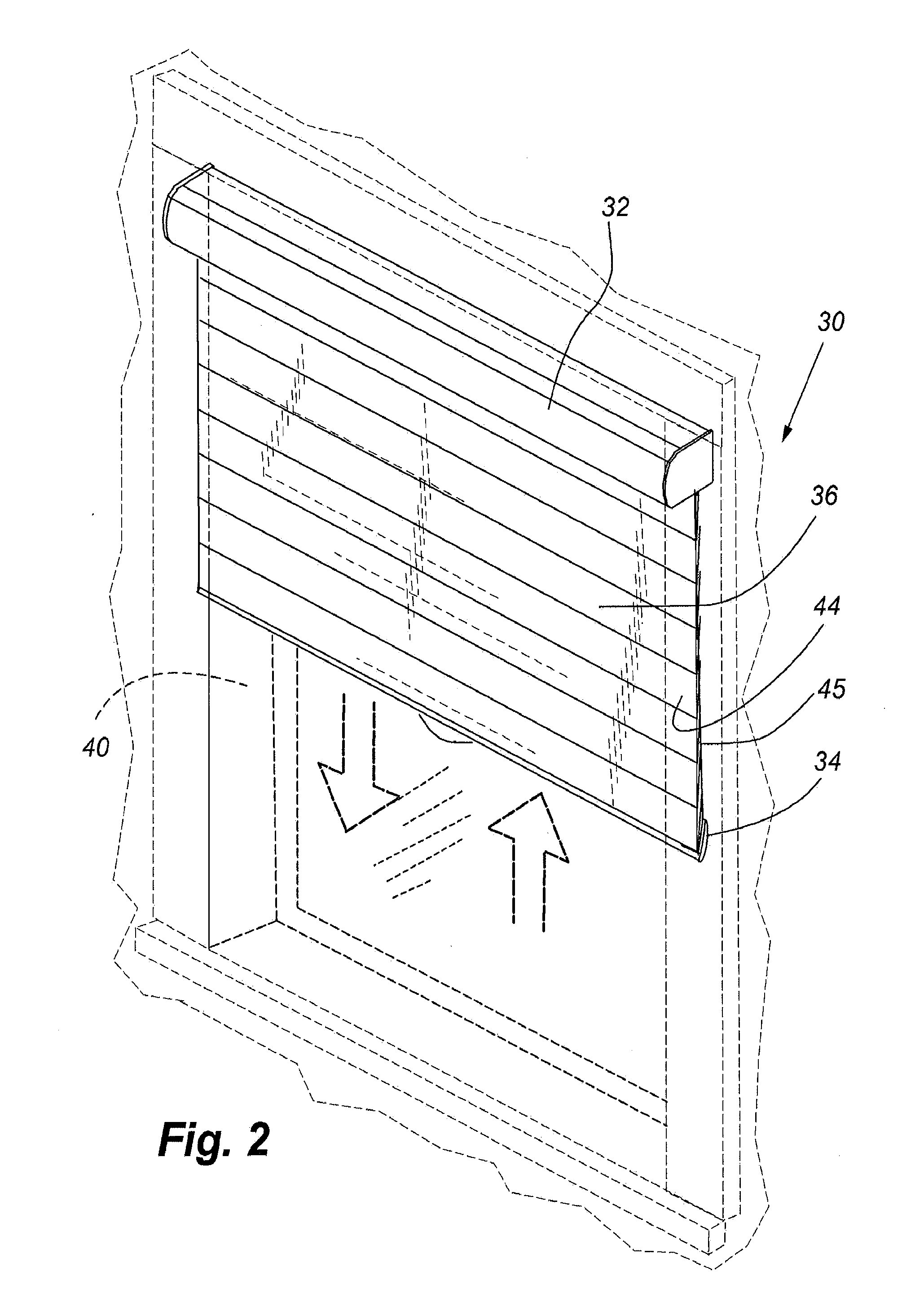
[0113]The present disclosure provides a retractable covering that includes a counterbalance that allows the shade material to be stopped at a number of different locations, selected by the user, along a drop length of the shade. Conventional cordless operating systems may generally have a finite number of stop positions for the extension of the shade and / or generally may be limited to shades in which the only function is to raise and lower, and are not capable of adjusting the graduated amount of light passing through the shading when in the fully extended position. As such, these systems are not capable of operating shades with a plurality of tiltable horizontal vanes. However, the covering and operating system of the present disclosure may provide for a shade that may vary light passage there through when in the fully extended position, as well as be positionable at substantially any position between full extension and full retraction.

[0114]Referring to FIGS. 1 and 2, the retracta...


PUM


Abstract

A cordless retractable shade including an operating system for the shade that varies a biasing force of a spring to counterbalance the shade. The bottom rail of a retractable shade can be raised or lowered, and due to the operating system remains in any selected position of the covering between fully extended and fully retracted, without the use of operating cords. The system includes a method of negating and reversing the spring bias effect at a strategic position whereby the flexible vanes of the shade can be adjusted between open and closed.

Description

CROSS REFERENCE TO RELATED APPLICATIONS[0001]This patent Cooperation Treaty patent application claims priority to U.S. Provisional Patent Application No. 61 / 527,820 filed 26 Aug. 2011 entitled “Cordless Retractable Roller Shade for Window Coverings,” the contents of which are incorporated herein by reference in its entirety.TECHNICAL FIELDField[0002]The present disclosure relates generally to retractable shades for architectural openings and more particularly to such a shade that does not include operating or lift cords, but rather is operable between selected extended conditions of the shade by manual movement of the bottom rail of the shade.BACKGROUNDDescription of the Relevant Art[0003]Retractable shades have been popular for many years and generally extend across or are retracted from covering architectural openings such as windows, doorways, archways, and the like. Such retractable coverings may include a roller rotatably supported with a shade material suspended therefrom. The...

Claims


Application Information

Patent Timeline
Patent Type & Authority Applications(United States)
IPC IPC(8): E06B9/38
CPCE06B9/38E06B9/262E06B2009/2627E06B2009/2435E06B2009/3222E06B9/24E06B9/40E06B9/60E06B9/44E06B9/90E06B9/42E06B9/58E06B9/80E06B9/264E06B9/322E06B9/56
Inventor SMITH, STEPHEN P.SMITH, KENT A.RHODES, GALEN B.WINTERS, STEPHEN M.FALLER, KENNETH M.
Owner HUNTER DOUGLAS INC
Why Eureka
Try Eureka