
Control of Energy Storage System Inverter System in a Microgrid Application

a technology of energy storage system and microgrid, which is applied in the direction of electric variable regulation, process and machine control, instruments, etc., can solve the problems of energy storage system (ess) not having the capacity to support grid support, and energy storage system (ess) presenting additional requirements for long-term charge maintenance and ess component protection

Active Publication Date: 2014-08-07
CATERPILLAR INC
View PDF9 Cites 38 Cited by
  • Summary
  • Abstract
  • Description
  • Claims
  • Application Information

AI Technical Summary

Benefits of technology

This patent describes a system, method, and apparatus for managing power transfer with a power grid using a DC link, an energy storage system, and a load controller. The load controller includes a DC-to-AC inverter that can adjust its output frequency based on the frequency of the power grid and the power transfer state of the load controller. The system can also include a DC-to-DC converter that controls the current magnitude and direction based on the voltage on the DC link and the voltage at the energy storage system, providing multiple charging and discharging modes. The technical effect of this patent is to improve the efficiency and reliability of power transfer between the energy storage system and the power grid.

Problems solved by technology

In this environment, power generation levels, frequency, and voltage may vary in a wide range due to the volatile nature of some of the power sources and sluggish response times of generator sets.
Statcom systems may not have the capacity for grid support over the longer durations that may be occur in micro grid applications.
However, energy storage systems (ESS) present additional requirements for long-term charge maintenance and ESS component protection.

Method used


Image

  • Control of Energy Storage System Inverter System in a Microgrid Application
  • Control of Energy Storage System Inverter System in a Microgrid Application
  • Control of Energy Storage System Inverter System in a Microgrid Application

Examples


Embodiment Construction

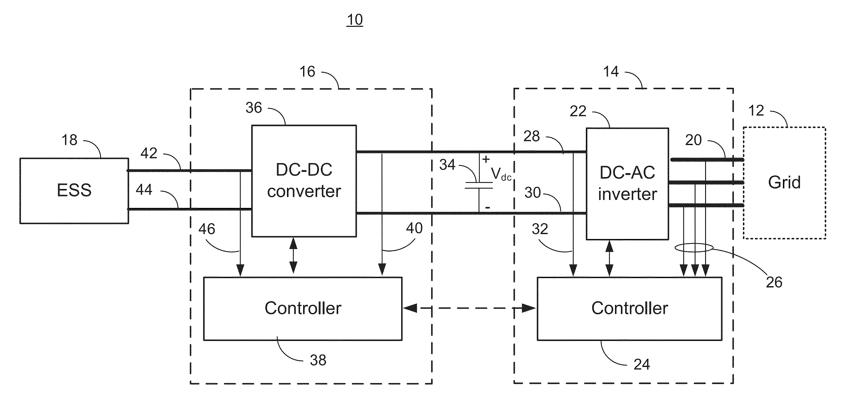
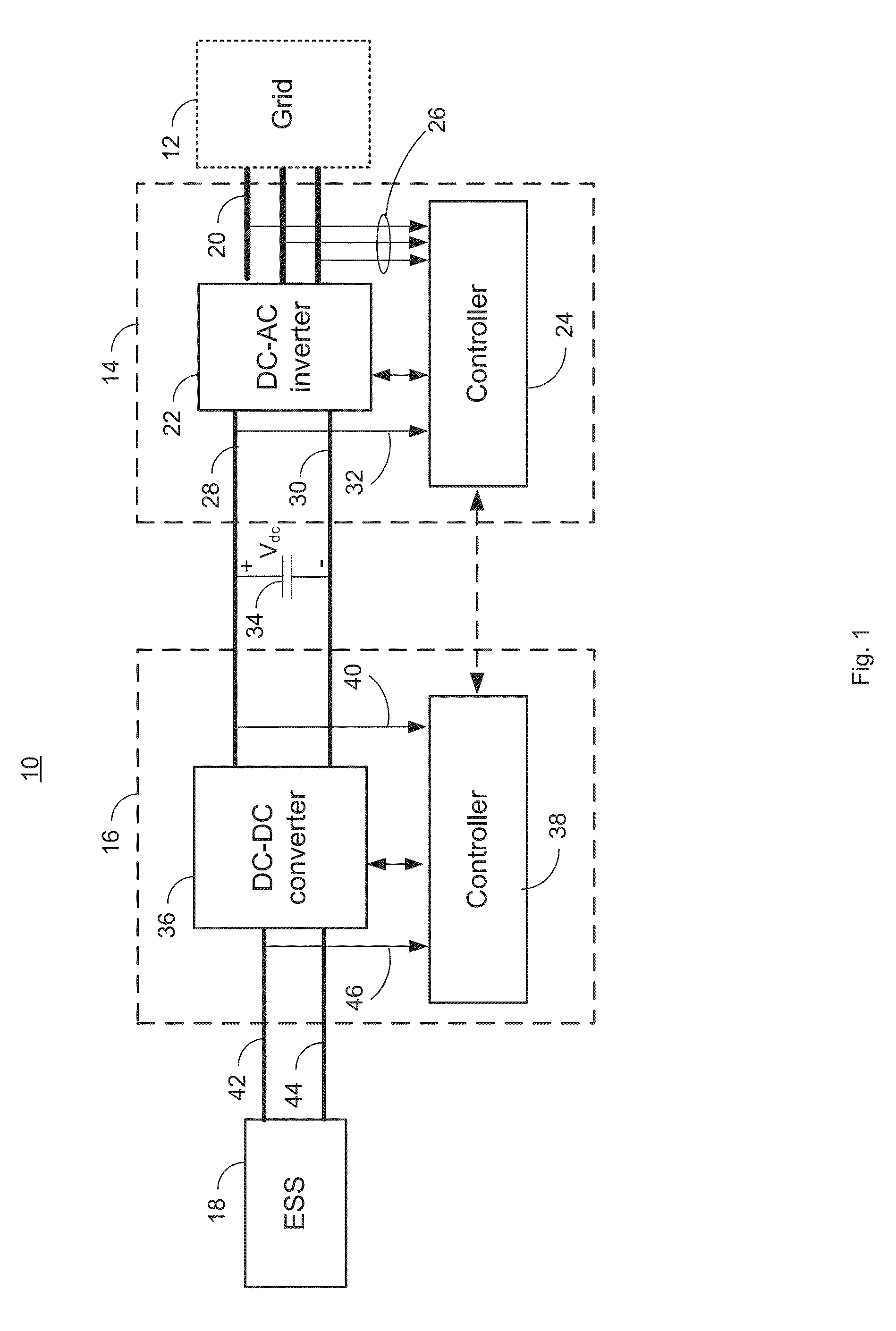
[0020]FIG. 1 is a block diagram illustrating a system 10 for managing power transfer with a grid 12. The system 10 includes a load manager 14, an energy storage system manager 16, and an energy storage system (ESS) 18. The grid 12 may be a microgrid and may include both loads and power sources (not depicted). The power sources may include solar panels, wind turbines, diesel or gas generator sets, fuel cells, and / or the utility grid. In an embodiment, the primary power source is a bank of fossil fuel generators. As the demand for power on the grid 12 increases, additional generators may be brought on line. In an embodiment, a nominal or target operating range of the grid may be 440 VAC ±5% and 60 Hz±0.5 Hz. In other embodiments, other operating voltages, frequencies and nominal tolerances may be used. As will be discussed below, even though these represent target ranges operation outside these target ranges may occur for a number of reasons and may require steps to help bring operati...


PUM


Abstract

A system that manages a supplemental energy source connected to a power grid uses a two stage control strategy to manage power transfers in and out of the power grid as well as in and out of an energy storage system, such as a battery bank. One stage uses a non-linear transfer function to control an output frequency of a DC-to-AC inverter to limit undesired effects of power transients that occur on the grid. A second stage uses control strategy for transferring energy between the energy storage system and an internal DC link based on a relationship between a voltage on a DC link connecting the first and second stages and a DC link reference voltage, the voltage on the DC link, and a voltage at the energy storage system. The control strategy includes rapid charging, over-charging protection, and grid transient stabilization.

Description

TECHNICAL FIELD[0001]The present disclosure relates to electrical power equipment and more specifically to an energy storage system inverter apparatus used in micro grid applications.BACKGROUND[0002]The frequency of a grid, particularly a large or “infinite” grid is relatively stable. All synchronous generators on the grid will synchronize to the grid frequency. Load on the grid is inversely proportional to grid frequency, so that as the load increases relative to the combined generator output, grid frequency decreases.[0003]Droop frequency control is used in such synchronous generators to control power output. When a reference frequency is above a grid frequency, power is added to the prime move, e.g., more fuel is provided to an engine driving the generator, so that torque is increased and more power is output. Droop control systems use a linear function around the desired power level to manage the frequency of the output as a function of power.[0004]Statcom systems are used in th...

Claims


Application Information

Patent Timeline
Patent Type & Authority Applications(United States)
IPC IPC(8): H02M7/537G05F1/46
CPCG05F1/46H02M7/537H02J3/24H02J3/32H02M3/1584H02M7/797H02M2001/007Y02P80/14H02J3/241H02M1/007
Inventor YU, DACHUANSPECKHART, GREG
Owner CATERPILLAR INC
Learn More