Battery assembly

a battery and assembly technology, applied in the field of battery assemblies, can solve problems such as inhibiting efficient cooling, and achieve the effects of efficient cooling, uniform cooling efficiency, and efficient cooling of unit cells

a battery and assembly technology, applied in the field of battery assemblies, can solve problems such as inhibiting efficient cooling, and achieve the effects of efficient cooling, uniform cooling efficiency, and efficient cooling of unit cells

US20140220404A1Inactive Publication Date: 2014-08-07GS YUASA INT LTD

Image

  • Battery assembly
  • Battery assembly
  • Battery assembly

Examples


Embodiment Construction

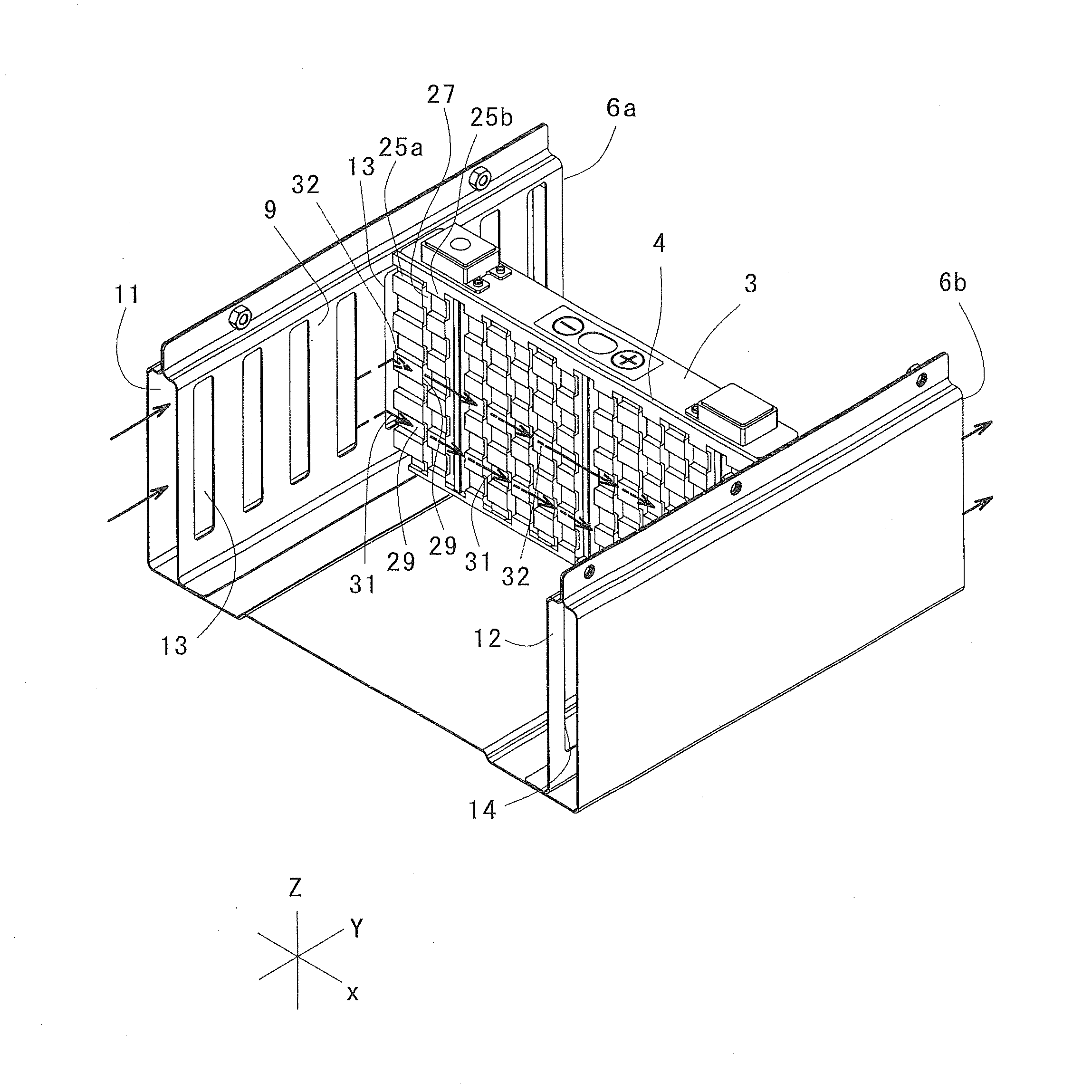
[0046]Preferred embodiments according to the present invention will be described with reference to the attached drawings. In the present specification, an X-axis and a Y-axis are set perpendicularly to each other on a horizontal plane whereas a Z-axis is set on a vertical plane perpendicular to the X- and Y-axes for the sake of explanation, as shown in FIG. 1. Directions parallel to the X-, Y-, and Z-axes are referred to as an X-direction, a Y-direction, and a Z-direction, respectively.

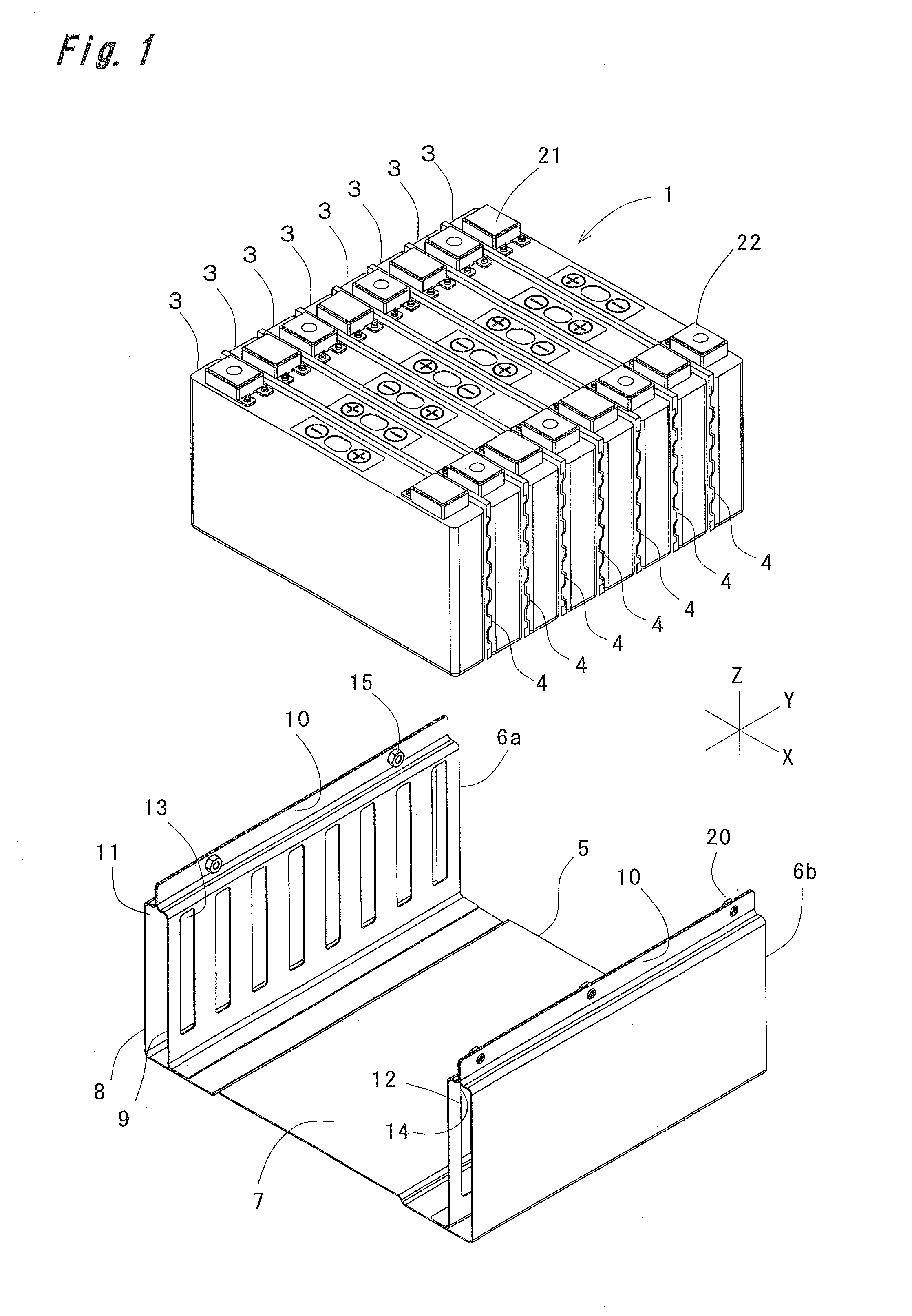
[0047]FIG. 1 shows a battery assembly 1 according to a preferred embodiment of the present invention. In the battery assembly 1, a plurality of unit cells 3 are juxtaposed in a stack case 2, and further, spacers 4 are held between the unit cells 3.

[0048]The stack case 2 is made of a steel plate. The stack case 2 includes a rectangular bottom plate 5 extending in the X- and Y-directions and a left wall 6a and a right wall 6b erected in the Z-direction at both ends in the X-direction of the bottom plate...


PUM


Abstract

A spacer interposed between first and second unit cells has alternately arranged first and second corrugated portions. Each of the corrugated portions has first and second protrusions alternately and repeatedly formed continuously in a vertical direction. Each of the first protrusions protrudes from a center in a thickness direction toward the first unit cell so as to define a clearance functioning as a cooling passage between the second unit cell and the first protrusion. Each of the second protrusions protrudes from the center in the thickness direction toward the second unit cell so as to define a clearance functioning as a cooling passage between the first unit cell and the second protrusion. The arrangement phases of the first and second protrusions are different from each other in the first and second corrugated portions. A cooling medium flowing in the cooling passages is alternately brought into contact with the first and second unit cells, thus achieving the uniform cooling efficiency with respect to the unit cells.

Description

TECHNICAL FIELD[0001]The present invention relates to a battery assembly having a plurality of unit cells combined with each other and, more particularly, to the structure of a spacer held between unit cells.BACKGROUND ART[0002]There has been conventionally known a structure in which a spacer is held between unit cells in a battery assembly so as to form a cooling passage, through which a cooling medium passes, so that the cooling medium passing the cooling passage cools the unit cells that generate heat by repeated electric charging / discharging.[0003]Patent literature 1 discloses a spacer held between battery modules. In the spacer, first abutting portions that abut against a first battery module out of two adjacent battery modules and second abutting portions that abut against a second battery module are alternately disposed, and thus, cooling passages in which the first battery module is brought into contact with a cooling medium and other cooling passages in which the second bat...

Claims


Application Information

Patent Timeline
07 Aug 2014
Publication
US20140220404A1
IPC
H01M10/6557; H01M50/209; H01M50/224; H01M50/291
CPC
H01M10/5059; H01M50/291; H01M50/209; H01M50/224; H01M10/647; H01M10/6557; H01M10/6566; H01M10/613
Inventors
MASUDA, YOSHIHIRO; YOSHIOKA, TOSHIKI