Devices and methods for visually indicating the alignment of a transcutaneous energy transfer device over an implanted medical device

a technology of transcutaneous energy transfer and alignment indicator, which is applied in the direction of battery data exchange, exchanging data charger, therapy, etc., can solve the problems of affecting the efficiency of transcutaneously inducing a current in the implanted coil, unable to accurately align the tet coil and charging coil without the aid of an alignment indicator, and unable to determine whether the efficiency of energy transfer is maximized

Active Publication Date: 2014-08-07
CIRTEC MEDICAL CORP
View PDF3 Cites 56 Cited by
  • Summary
  • Abstract
  • Description
  • Claims
  • Application Information

AI Technical Summary

Benefits of technology

[0028]In an embodiment, the circuitry and the visual display are implemented inside a handheld control device, and the handheld control device is electrically coupled to the coil assembly structure through a conductive cable.
[0029]One more of the broader forms of the present disclosure involves an apparatus for charging a medical device implanted in a body tissue. The apparatus includes: coil assembly means for transcutaneously delivering electrical power to the implanted medical device, wherein the coil assembly

Problems solved by technology

For example, the efficiency of transcutaneously inducing a current in the implanted coil is detrimentally affected if the external TET coil and implanted coil are not properly aligned.
Though the operator of the TET device may use the visual or tactile signs of implantation to approximate the location of the IPG, precise alignment of the TET coil and charging coil is extremely difficult without the aide of an alignment indicator.
Because there is no physical connection between the external TET device and the IPG to provide feedback, ascertaining whether the efficiency of energy transfer is maximized is problematic.
Even if the TET device is properly aligned with the IPG at the initiation o

Method used


Image

  • Devices and methods for visually indicating the alignment of a transcutaneous energy transfer device over an implanted medical device
  • Devices and methods for visually indicating the alignment of a transcutaneous energy transfer device over an implanted medical device
  • Devices and methods for visually indicating the alignment of a transcutaneous energy transfer device over an implanted medical device

Examples


Embodiment Construction

[0057]For the purposes of promoting an understanding of the principles of the present disclosure, reference will now be made to the embodiments, or examples, illustrated in the drawings and specific language will be used to describe the same. It will nevertheless be understood that no limitation of the scope of the present disclosure is thereby intended. Any alterations and further modifications in the described embodiments, and any further applications of the principles of the present disclosure as described herein are contemplated as would normally occur to one skilled in the art to which the present disclosure relates.

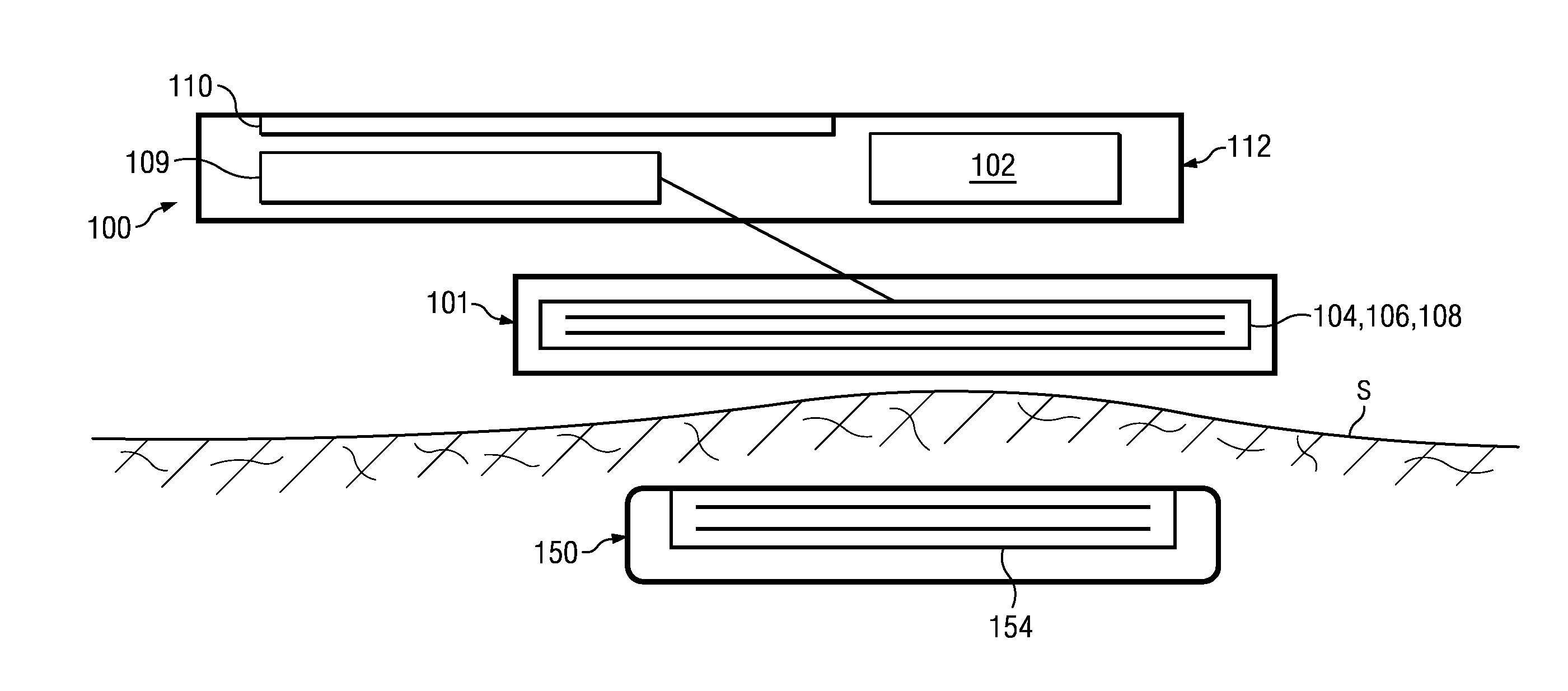
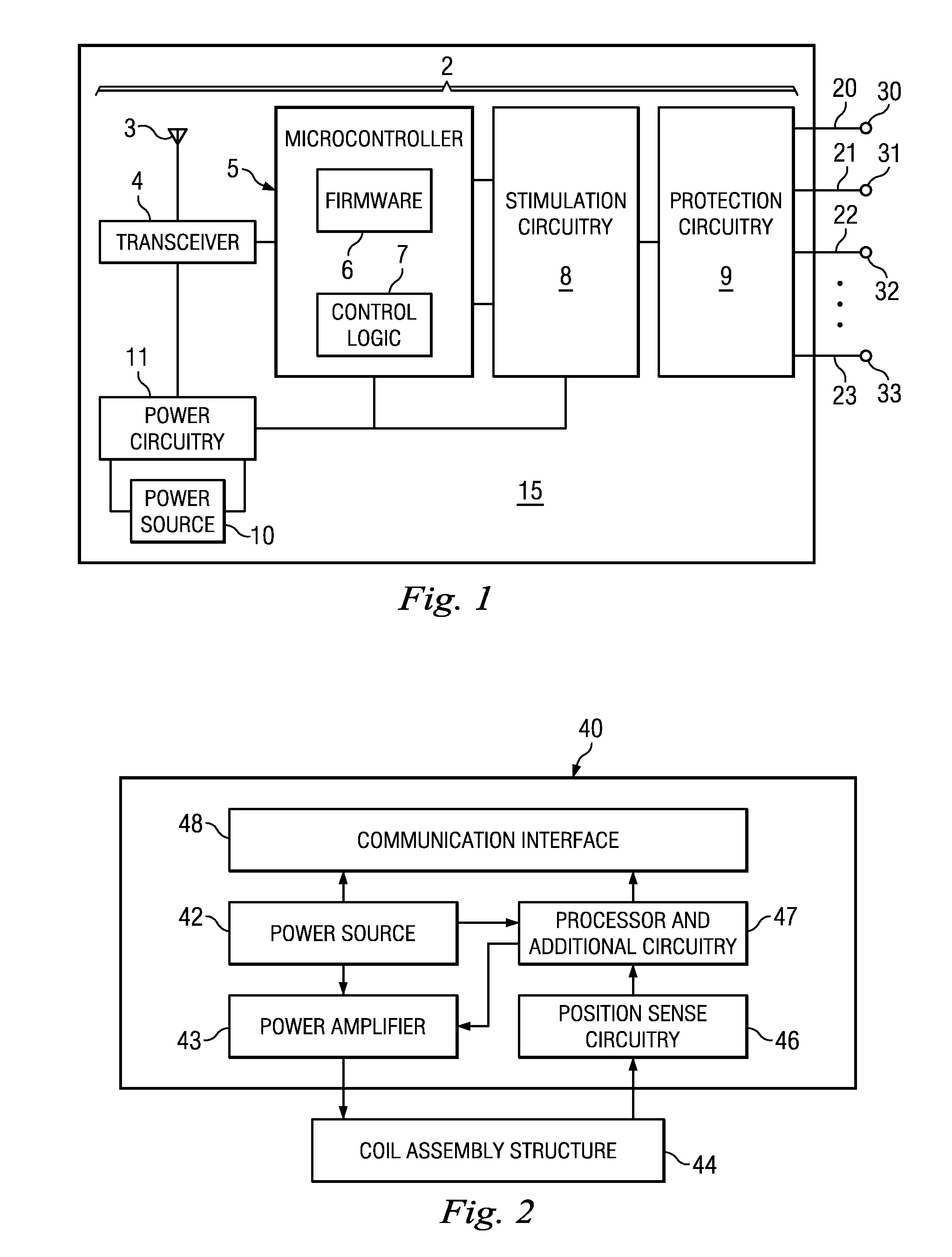
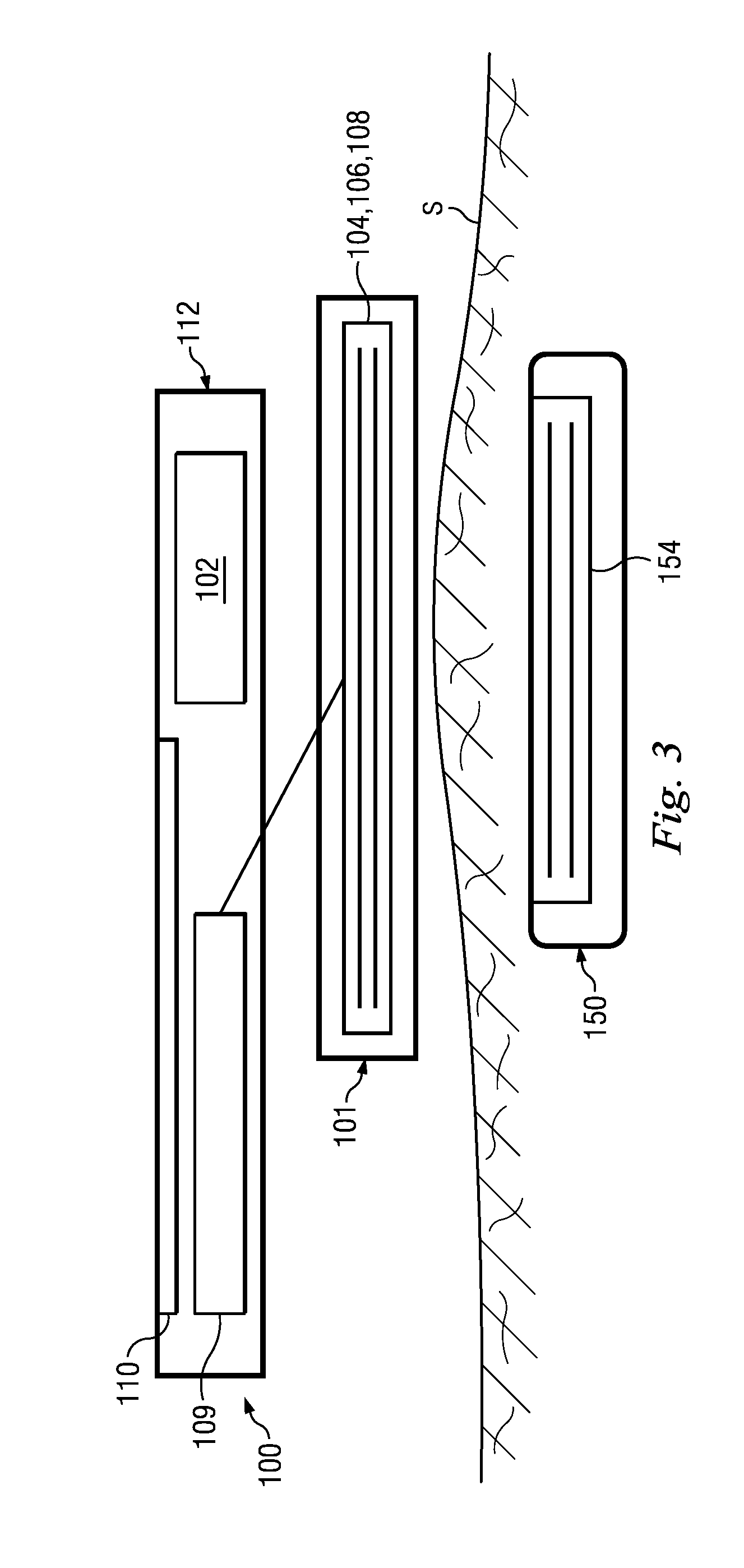
[0058]FIG. 1 is a simplified diagrammatic view of an embodiment of a neurostimulator device 2. The neurostimulator device 2 includes an antenna 3 and a transceiver 4 coupled to the antenna 3. The antenna 3 is capable of sending signals to an external device and receiving signals from the external device. The transceiver 4 contains transmitter circuitry and receiver ...


PUM


Abstract

The present disclosure involves a charging system for charging an implanted medical system. The charging device includes a replenishable power supply. The charging device includes a coil assembly electrically coupled to the power supply. The coil assembly includes a primary coil and a plurality of sense coils positioned proximate to the primary coil. The charging device includes electrical circuitry operable to: measure an electrical parameter of the coil assembly; and determine a position of the coil assembly relative to a position of the implanted medical device based on the measured electrical parameter. The charging device includes a visual communications interface operable to: receive an input from the electrical circuitry; and visually display on a screen the position of the coil assembly relative to the position of the implanted medical device based on the input received from the electrical circuitry.

Description

PRIORITY DATA[0001]The present application is a continuation application of U.S. patent application Ser. No. 13 / 185,636, filed on Jul. 19, 2011, entitled “Devices and Methods for Visually Indicating the Alignment of a Transcutaneous Energy Transfer Device Over an Implanted Medical Device”, the disclosure of which is hereby incorporated by reference in its entirety.BACKGROUND[0002]Implantable medical devices for producing a therapeutic result in a patient are well known. The implanted medical device often requires electrical power to perform its therapeutic function. This electrical power is derived from a power source. There are many kinds of powered, implantable medical devices that are powered by an external power source. It is recognized that other implantable medical devices are envisioned which also utilize energy transferred from or delivered by an external source.[0003]By way of example, one type of powered, implantable medical device is a neurostimulation device. Neurostimul...

Claims


Application Information

Patent Timeline
IPC IPC(8): A61N1/378
CPCA61N1/3787A61N1/37247H02J7/00034H02J50/005H02J50/90H02J50/10H02J2310/23
Inventor FELL, ROGER B.
Owner CIRTEC MEDICAL CORP
Why Eureka
Try Eureka