Air filter element

a filter element and air technology, applied in the field of filter system, can solve the problems of becoming more and more difficult to apply the torque, and achieve the effect of ensuring safety, ensuring safety, and extending the service life of the actual filter elemen

Active Publication Date: 2014-08-14
MANN HUMMEL GMBH
View PDF3 Cites 23 Cited by
  • Summary
  • Abstract
  • Description
  • Claims
  • Application Information

AI Technical Summary

Benefits of technology

[0019]Advantageously, in the area of the inlet of the filter system a cyclone separator can be provided and a dirt outlet can be provided on the housing or on the cover. This cyclone separator is comprised of a guiding geometry that causes the medium to be filtered to rotate. Due to this rotation, the dirt in the area of the housing wall is concentrated and is then discharged at a suitable location by means of a dirt outlet. Due to the preseparation of most of the dirt from the air to be filtered, the service life of the actual filter element can be extended decisively.
[0020]In a further advantageous embodiment, an inlet and / or dirt outlet arranged at the cover can be designed as a grip lever. In this way, it is possible by lever action to apply a greater torque onto the elements to be released upon rotation of the cover; this may be of great importance in particular for very large filter systems or greatly soiled filter systems where the screw connections may possibly be stuck (“frozen”).
[0021]Expediently, the filter system can be used as an air filter, in particular an air filter of an internal combustion engine. Safe operation of internal combustion engines is also based on a reliable and favorable filtration of the intake air for combustion. The described filter element provides an economic possibility for this purpose.
[0022]Advantageous is also the use of the filter system as a particle filter, in particular as an oil filter or fuel filter of an internal combustion engine. In this context, reliable mounting and economical replacement of the described filter element are of decisive importance.
[0023]The invention concerns as a further aspect a filter element for installation in a filter system as described above, wherein the filter element is exchangeably arranged in the housing of the filter system. Advantageously, in a service situation for exchange of the filter element, a tool integrated into the cover of the housing of the filter system can be used for releasing and tightening the filter element. In this way, the tool is always available on site in a service situation and cannot be lost.
[0024]Furthermore, the invention concerns a secondary element for installation in a filter system as described above, wherein the secondary element is exchangeably arranged in the housing of the filter system. Advantageously, when exchanging the secondary element in a service situation, a tool which is integrated into the cover of the housing of the filter system can be utilized for releasing and tightening the secondary element. In this way, the tool is always on site in a service situation and cannot be lost.

Problems solved by technology

Particularly in case of large elements it becomes however more and more difficult to apply the required torque.

Method used


Image

  • Air filter element
  • Air filter element
  • Air filter element

Examples


Embodiment Construction

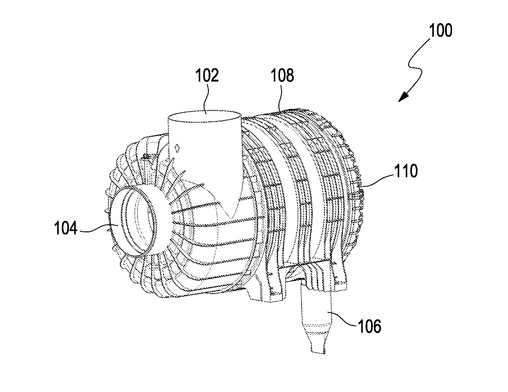
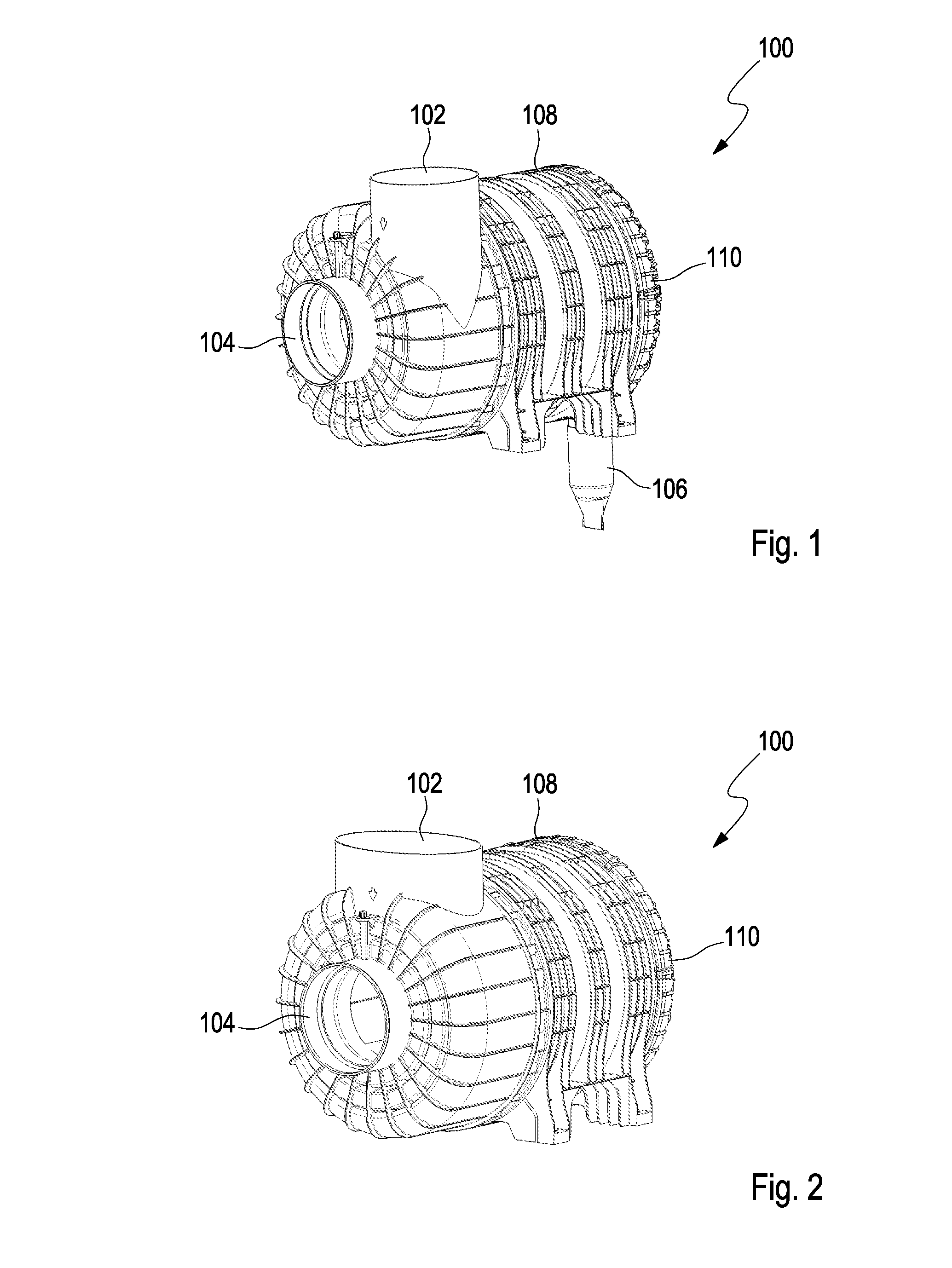
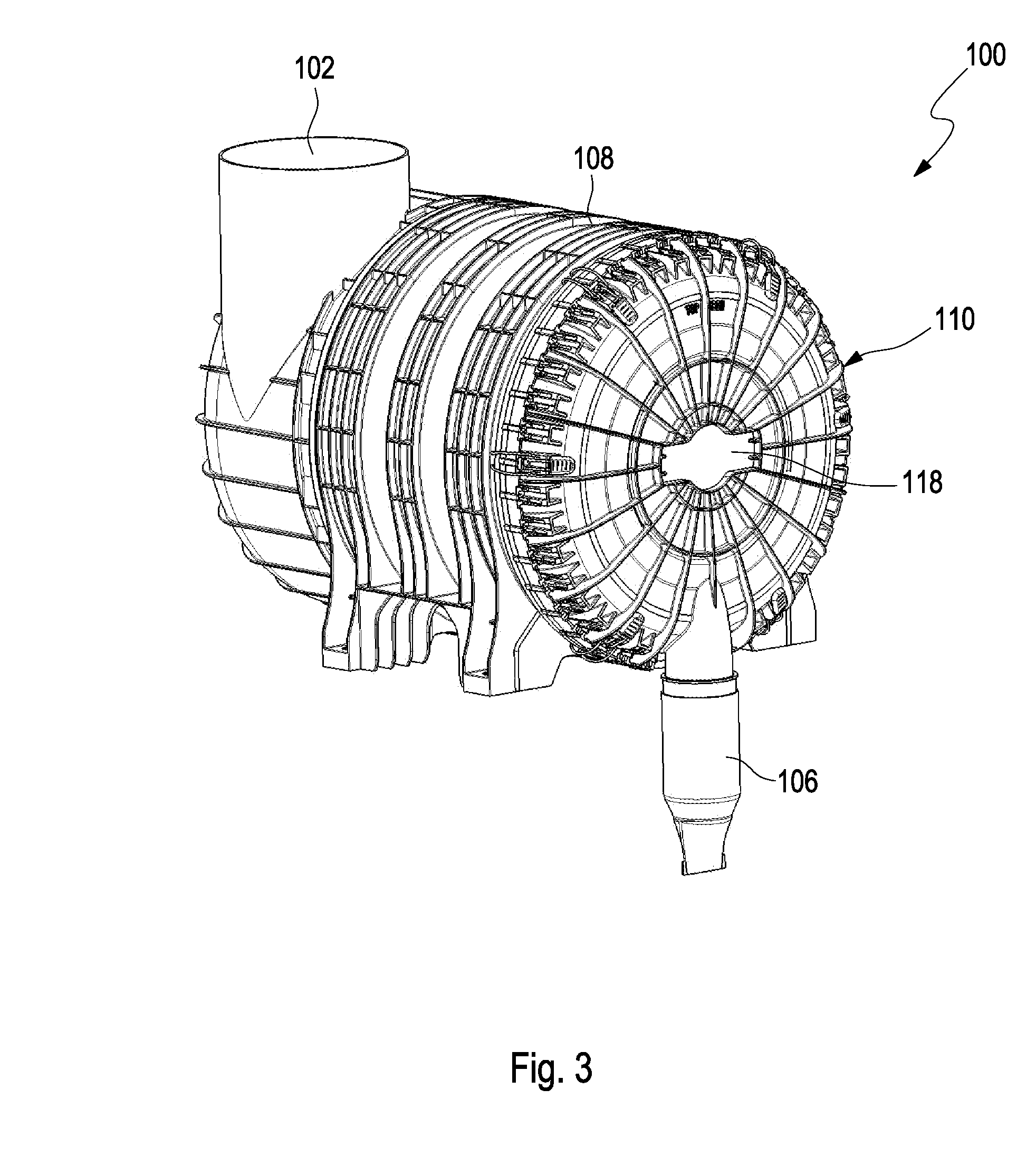
[0034]FIG. 1 shows in a perspective illustration a filter system 100 according to one embodiment of the invention with tangential inlet 102, central outlet 104, and dirt outlet 106 at the bottom. Illustrated is a round filter configuration which is comprised of a housing 108 that is closed off by cover 110. In case of an air filter system, dust-laden air flows into the inlet 102 that is arranged tangentially to the air filter element installed in the interior of the housing so that the air in the interior of the housing 108 is caused to rotate due to an incoming flow protector provided at the filter element. Filter element and incoming flow protector are not illustrated in the drawing. Due to the cyclone effect that is caused by the rotational movement of the air, centrifugal forces act on the dirt particles of the inflowing air so that the dirt particles are partially separated at the housing wall and can be discharged through the dirt outlet 106 from the filter system 100. In this...


PUM

PropertyMeasurementUnit
areaaaaaaaaaaa
torqueaaaaaaaaaa
timeaaaaaaaaaa

Abstract

A filter system has a housing and at least one detachable cover detachably connected to the housing to close off the housing. At least one exchangeable element is arranged within the housing and provided with a follower contour. The cover is provided with a follower tool which matches the follower contour of the at least one exchangeable element. The follower tool is disposed on the exterior side of the cover. The follower tool is a follower contour provided on the cover.

Description

CROSS-REFERENCE TO RELATED APPLICATIONS[0001]This application claims the benefit of U.S. Provisional Application No. 61 / 815,214 filed: Apr. 23, 2013. This application claims foreign priority under 35 USC 119(b) to prior filed German patent applications 10 2013 002 274.6 filed Feb. 12, 2013; 10 2013 002 275.4 filed Feb. 12, 2013; 10 2013 002 277.0 filed Feb. 12, 2013; 10 2013 002 278.9 filed Feb. 12, 2013; and 10 2013 002 276.2 filed Feb. 12, 2013, the entire contents of the aforesaid U.S. Provisional Application and the aforesaid German patent applications being incorporated herein by reference.BACKGROUND OF THE INVENTION[0002]The invention concerns a filter system, in particular for use as an air filter in an internal combustion engine, as well as a filter element for installation in such a filter system.[0003]WO 2009 / 047196 A1 discloses a filter system for internal combustion engines in which a secondary element is provided which is arranged in an inner space of the filter element...

Claims


Application Information

Patent Timeline
Patent Type & Authority Applications(United States)
IPC IPC(8): B01D46/00B01D50/00
CPCB01D50/002B01D46/0004F02M35/08B01D46/0041B01D46/2414B01D2265/021B01D2265/06B01D46/4227F02M35/084F02M35/0214F02M35/0223F02M35/02483F02M35/02416B01D50/20B01D46/64B01D46/0005B01D46/2411B01D46/523B01D45/16B01D46/88F02M35/0216F02M35/0245F02M35/02425F02M35/0205
Inventor KAUFMANN, MICHAELRUHLAND, KLAUS-DIETER
Owner MANN HUMMEL GMBH
Why Eureka
Try Eureka