Locking Bin Drawer with Slide-out Trays for Medications Cabinet

a locking bin and medication cabinet technology, applied in the field of cabinets, can solve the problems of not being able to limit the access of specific compartments in the drawer, the drawers divided into individual compartments with locking lids employing rather complex locking systems, and reducing the opportunity for the administration of a different medication for a given patien

Inactive Publication Date: 2014-08-14
S&S X RAY PRODS
View PDF11 Cites 26 Cited by
  • Summary
  • Abstract
  • Description
  • Claims
  • Application Information

AI Technical Summary

Benefits of technology

[0010]Accordingly, it is an object of the present invention to provide a medical dispensing arrangement that avoids the drawbacks of the prior art.
[0012]It is still another object to provide a cabinet that limits access to only one compartment of the drawer at a time, and which denies access to any other compartments at the time the drawer has been opened. This functionality is preferable, to limit access to only a single medication, and in doing so help reduce patient medication errors. It is also preferable for drawers containing narcotic medications to limit access to only the one medication prescribed.
[0015]Other objects include database control over the locations of the medications; fast retrieval of prescriptions; rapid and accurate fill of prescriptions; and database-provided restocking of medications.
[0019]The present invention individually locks each of the divided compartments within each drawer, allowing access to only one divided section of the drawer at a time. This allows only one medication to be available at one time to the pharmacy technician or nurse accessing the cabinet. The user will not have access to the entire contents of a drawer when opened. This reduces the opportunity for the administration of a different, wrong medication for a given patient.

Problems solved by technology

In some cases, only dividers are present in the drawers and it is then not possible to limit access for specific compartments within the drawer.
Until the present, drawers divided into individual compartments with locking lids have employed rather complex locking systems, with individual latches, releases and actuators for each compartment lid.
This reduces the opportunity for the administration of a different, wrong medication for a given patient.

Method used


Image

  • Locking Bin Drawer with Slide-out Trays for Medications Cabinet
  • Locking Bin Drawer with Slide-out Trays for Medications Cabinet
  • Locking Bin Drawer with Slide-out Trays for Medications Cabinet

Examples


Embodiment Construction

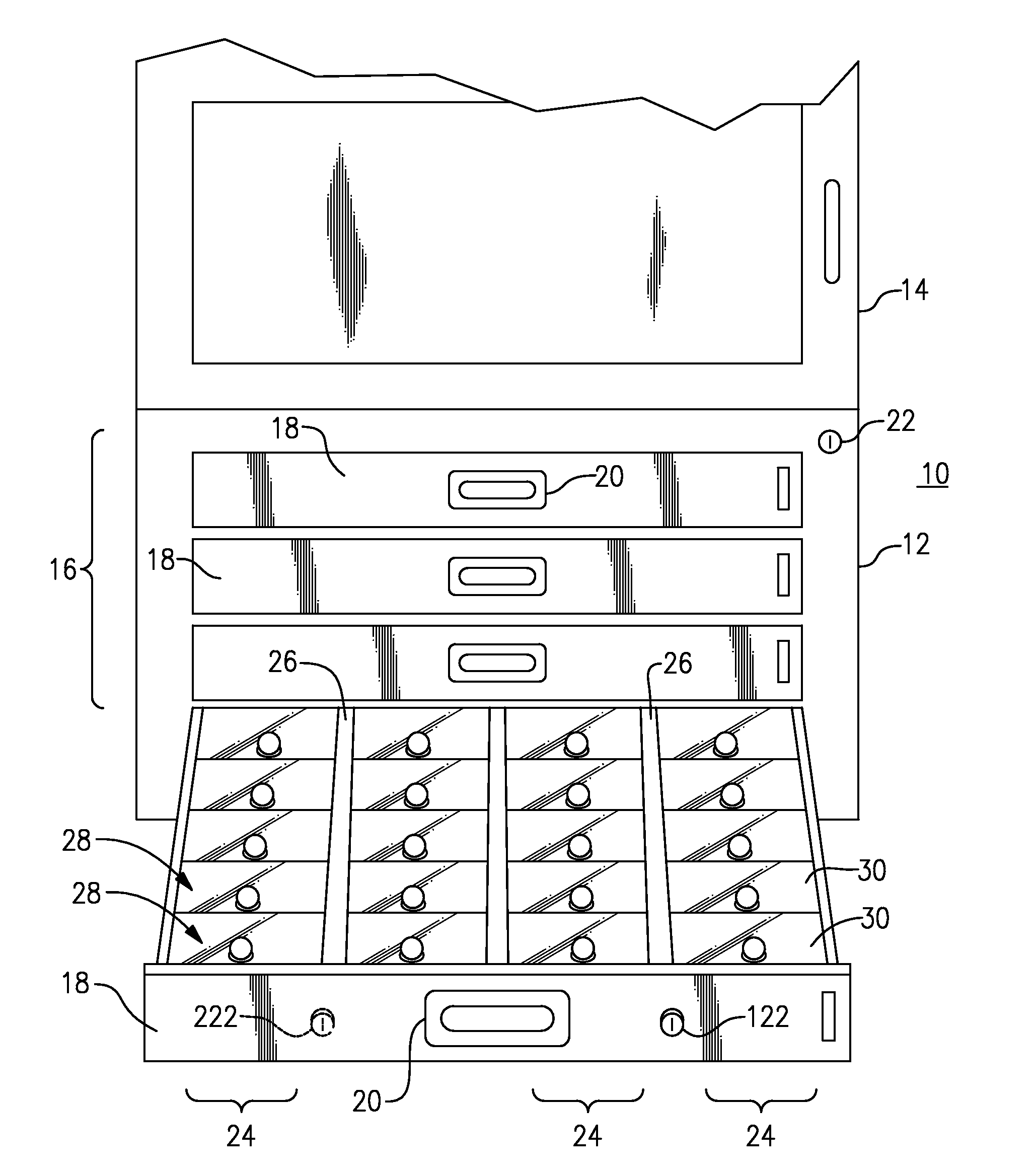
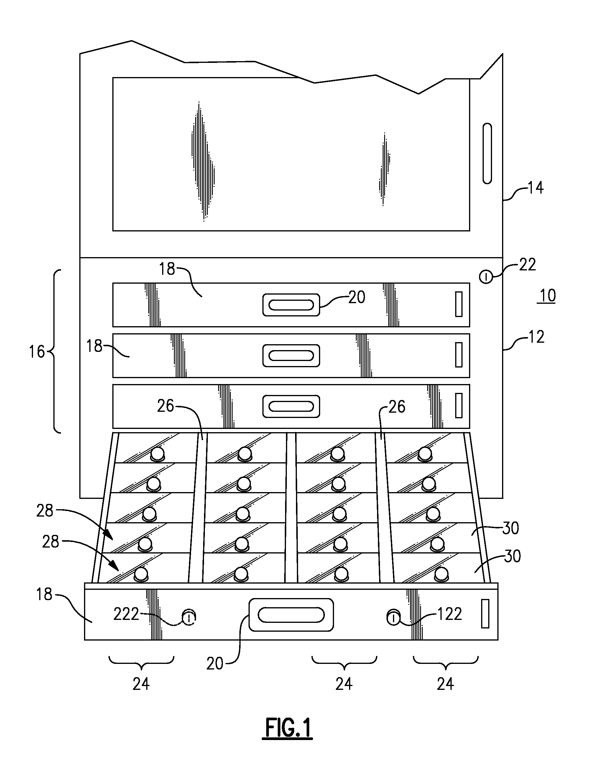
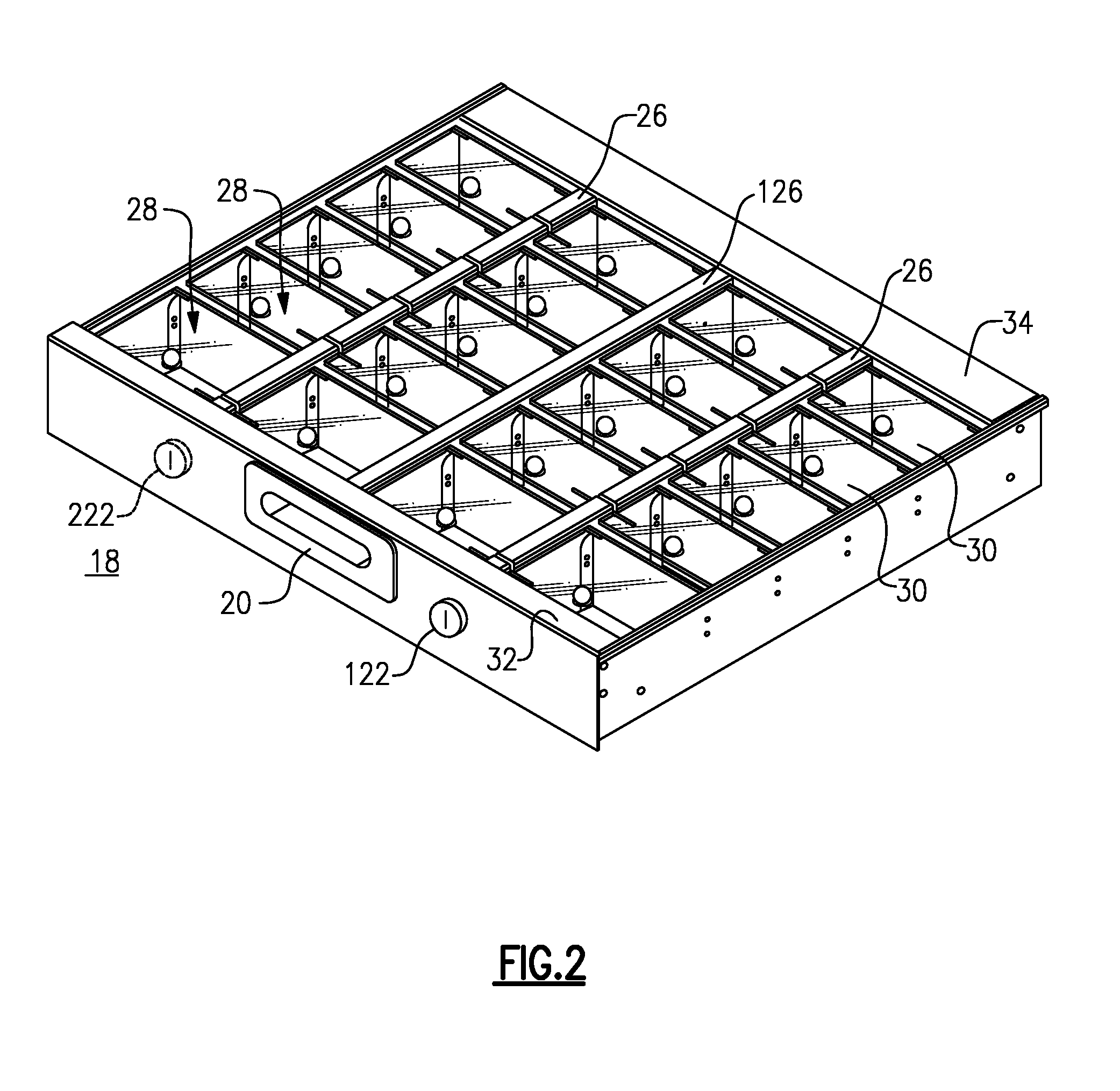
[0036]With reference to the Drawing, and initially to FIGS. 1 to 4, a medication dispensing cabinet 10 can be a free-standing cabinet, wall-mounted cabinet, or portable cabinet mounted on wheels, and here has a generally vertical frame 12 having an upper storage compartment 14 with a locking swing-open door and below that a rack 16 of pull out drawers 18. Here one drawer 18 is shown as having been pulled open. There is a handle or pull 20 at the proximal end or front of the drawer 18. A key-operated lock 22 may be located on the cabinet and can serve as a pharmacy over-ride or emergency override. The drawer 18 is divided into individual locked compartments, here arranged as four rows or files 24, with a divider channel 26 between a left-side pair of rows 24 and a similar divider channel 26 between the rows 24 of a right-side pair. A middle divider channel 126 separates the second and third rows of compartments. Each row 24 has a series of compartments 28, each of which has a pivoted...


PUM


Abstract

A controlled access pharmaceutical storage cabinet has at least one pull-out drawer that is divided into a number of locked compartments, arranged in rows. Each row of compartments can be configured as a slide-out tray. A slide bar lock is positioned between rows of the compartments, and has a series of slots along each edge which align with lock pins on hinged lids or covers for the compartments. Only one compartment can be opened at a time. A gear-motor is provided for each slide bar to move the slide bar to a position for access to a given compartment. A locking hinged front door panel can swing down to allow the trays to slide out under the locked lids for refilling or replacement.

Description

[0001]This is a continuation-in-part of my co-pending application Ser. No. 13 / 291,462, filed Nov. 8, 2011.BACKGROUND OF THE INVENTION[0002]This invention relates to cabinets for storing and dispensing prescription medications, non-prescription pharmaceuticals, medical supplies and other similar items for patient care in a hospital, clinic, nursing home, or similar health care facility. The invention is more specifically directed to a medical dispensing cabinet, with one or more pull-out drawers in which medical items are stored in individual compartments, which compartments may have locking lids or covers. The invention is more particularly concerned with a cabinet with limited access and with accountability of access and dispensing, and which may assist in the prevention of fraudulent access and reduction of medical errors. The cabinet drawer features trays that can slide out from beneath locked lids to facilitate restocking.[0003]In any hospital or clinic, or in wards or floors of...

Claims


Application Information

Patent Timeline
Patent Type & Authority Applications(United States)
IPC IPC(8): A61J7/00A47B96/00A47B81/00A47B88/20
CPCA61J7/0069A47B81/00A47B67/02A47B96/00A47B88/20A47B2210/08E05B47/0012E05B65/462E05B2047/0068A47B63/00A47B88/994A47B88/90
Inventor SHOENFELD, NORMAN A.
Owner S&S X RAY PRODS
Why Eureka
Try Eureka