
Multiple access point laser communications terminal

a laser communication terminal and access point technology, applied in the field of multi-access point laser communication terminals, can solve the problems of long-standing weather conditions, associated costs and penalties for swapping (size, weight and power), and long-standing loss of throughpu

Active Publication Date: 2014-08-14
RAYTHEON CO
View PDF18 Cites 7 Cited by
  • Summary
  • Abstract
  • Description
  • Claims
  • Application Information

AI Technical Summary

Benefits of technology

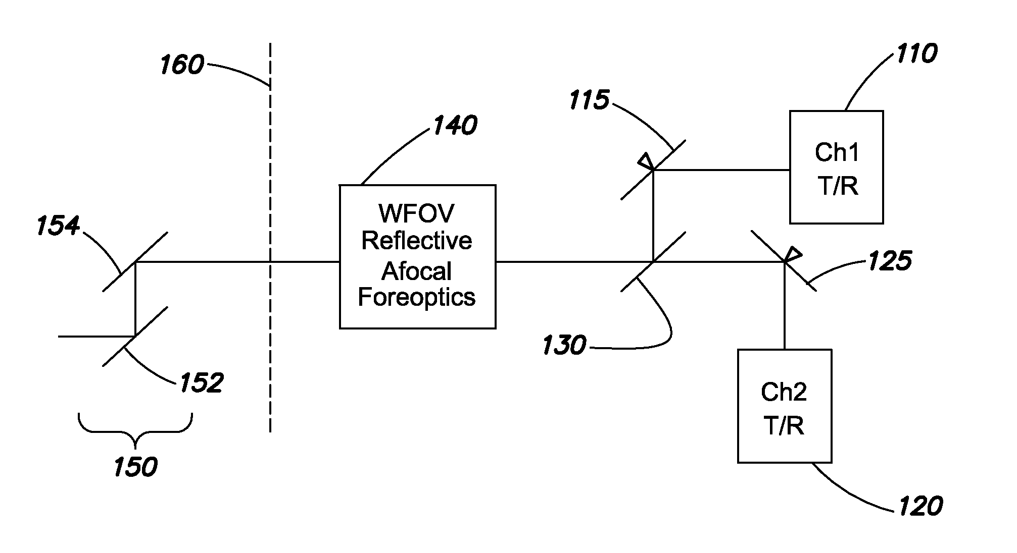
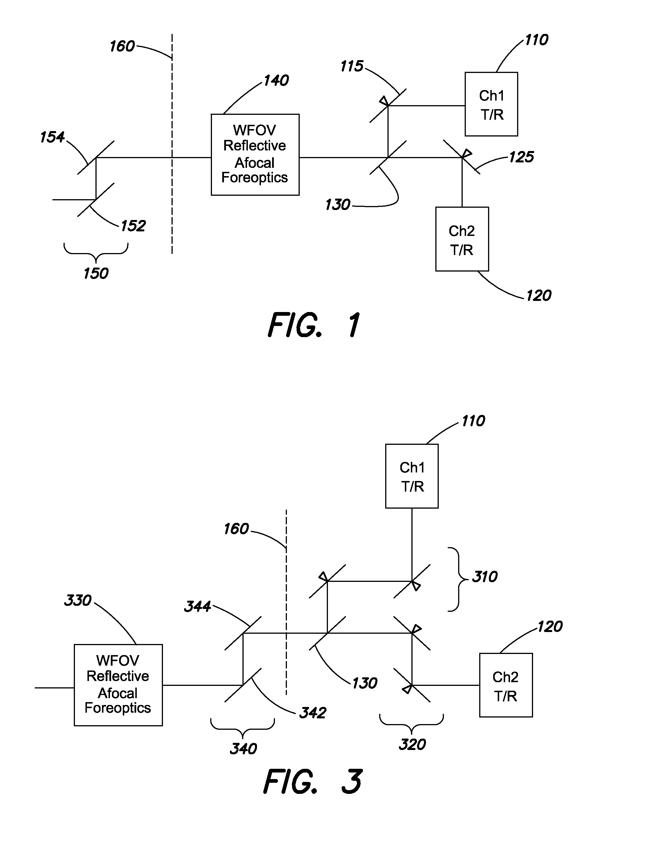
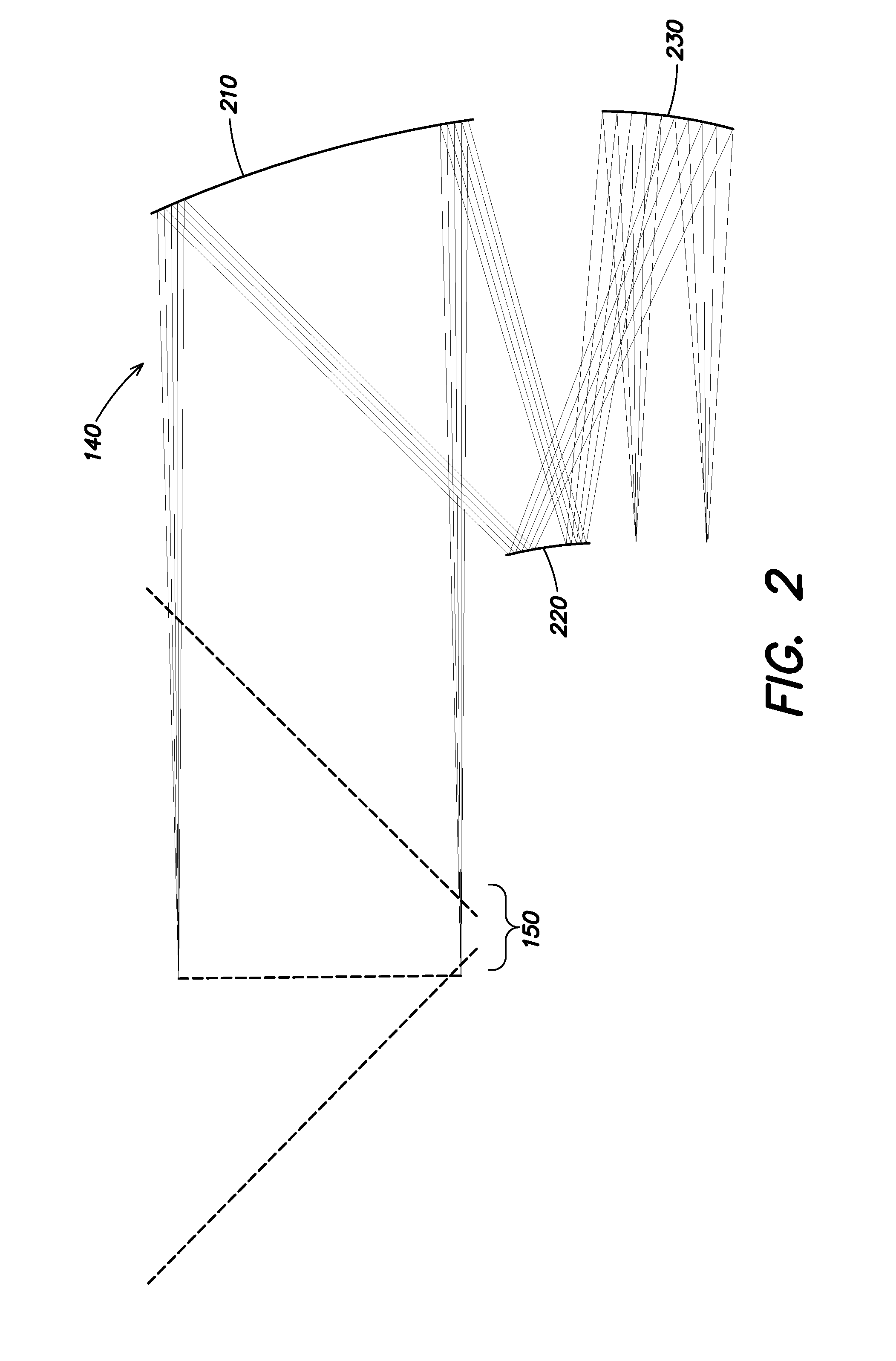
The patent describes an advanced laser communications terminal that can support multiple independent channels and steer optical signals over a wide field of view. The terminal includes a plurality of laser channels, each with a beam steering mirror to independently steer the optical signal. The laser channels can be mounted on a platform or gimbal, and the optical signals can be transmitted and received through an afocal telescope. The terminal can be used for laser communications with ground-based sites by directing the optical signals to the associated site using the beam steering mirrors. The method also includes monitoring beacon signals from the ground-based sites and selecting an alternate site if the beacon signal is not received. The technical effects of this patent include improved laser communications with multiple ground-based sites and greater flexibility in selecting the most suitable ground-based site for laser communications.

Problems solved by technology

For space-to-ground communications using a laser, weather conditions have long been a major issue.
Conventionally, weather mitigation often involves switching from laser-based communications to RF-based techniques, with an attendant loss in throughput.
However, each of these solutions has associated costs and SWAP (size, weight and power) penalties.
In addition, moving the terminal may result in unavoidable down-time in the communications system while the terminal is being moved.

Method used


Image

  • Multiple access point laser communications terminal
  • Multiple access point laser communications terminal
  • Multiple access point laser communications terminal

Examples


Embodiment Construction

[0013]Aspects and embodiments are directed to a laser communications (LC) terminal with the ability to simultaneously access multiple sites and provide advanced capability over conventional LC terminals that have very limited fields of view and the capability to access only a single site at any given time. As discussed above, weather phenomena can be a significant issue in the context of space-to-ground laser communications. However, most weather patterns are moderately localized. Statistically, the greater the ground separation between sites, the greater the likelihood that bad weather in one site will not correlate to similarly bad weather at an alternative site. Therefore, aspects and embodiments are directed to a laser communications terminal which can provide simultaneous two-way stabilized communications links to multiple ground sites separated on the ground by large distances, for example, hundreds of kilometers. These ground sites may be linked together, for example, using o...


PUM


Abstract

A laser communications terminal configured for simultaneous two-way stabilized communications links to multiple ground sites. One example of such a laser communications terminal includes a plurality of laser channels, each including a channel transceiver configured to transmit and receive an optical signal, an afocal telescope optically coupled to each of the channel transceivers, a celostat minor pair optically coupled to the afocal telescope, and a plurality of beam steering mirrors, at least one beam steering mirror associated with each channel of the plurality of laser channels and configured to independently steer the corresponding optical signal within a field of view of the afocal telescope.

Description

BACKGROUND[0001]For space-to-ground communications using a laser, weather conditions have long been a major issue. Laser communications are desirable since a laser channel may have far greater bandwidth, and therefore allow far greater data rates, than radio frequency (RF) channels. Conventionally, weather mitigation often involves switching from laser-based communications to RF-based techniques, with an attendant loss in throughput. Alternatively, weather-related problems may be addressed by using multiple laser communications terminals, each configured to access a single site since the terminals conventionally have a very small field of view (e.g., only a few microradians), or by attempting to move the terminal to another location to avoid the weather. However, each of these solutions has associated costs and SWAP (size, weight and power) penalties. In addition, moving the terminal may result in unavoidable down-time in the communications system while the terminal is being moved.S...

Claims


Application Information

Patent Timeline
Patent Type & Authority Applications(United States)
IPC IPC(8): H04B10/118
CPCH04B10/118H04B10/1127G02B17/0636G02B27/644
Inventor COOK, LACY G.
Owner RAYTHEON CO
Learn More