Manifold element for a filtering cartridge

a filtering cartridge and manifold element technology, applied in the field of filtering fluids, can solve the problems of increasing the overall cost, increasing the complexity of mounting, and being quite cumbersome, and achieve the effect of simple and reliable solution

Active Publication Date: 2014-08-21
UFI FILTERS SPA
View PDF13 Cites 7 Cited by
  • Summary
  • Abstract
  • Description
  • Claims
  • Application Information

AI Technical Summary

Benefits of technology

[0036]This aspect of the invention has the advantage of providing a particularly simple and reliable solution for providing the anti-disengagement safety means.

Problems solved by technology

Though being advantageous in terms of accumulation capacity, this type of filtering cartridges reveal the drawback of being quite complex to mount and being quite cumbersome.
The mounting difficulty is disadvantageous in that it makes the interventions of replacing the filtering cartridge—when clogged—difficult and slow thus also increasing the costs thereof.
The large overall dimension is disadvantageous in that it increases the overall dimensions of the filtering assembly which, on the contrary, should be generally small in size and / or meet precise dimensional and geometric requirements that are established by vehicle manufacturers, depending on the distribution of the volumes of all components within the vehicle engine compartment.

Method used


Image

  • Manifold element for a filtering cartridge
  • Manifold element for a filtering cartridge
  • Manifold element for a filtering cartridge

Examples


Embodiment Construction

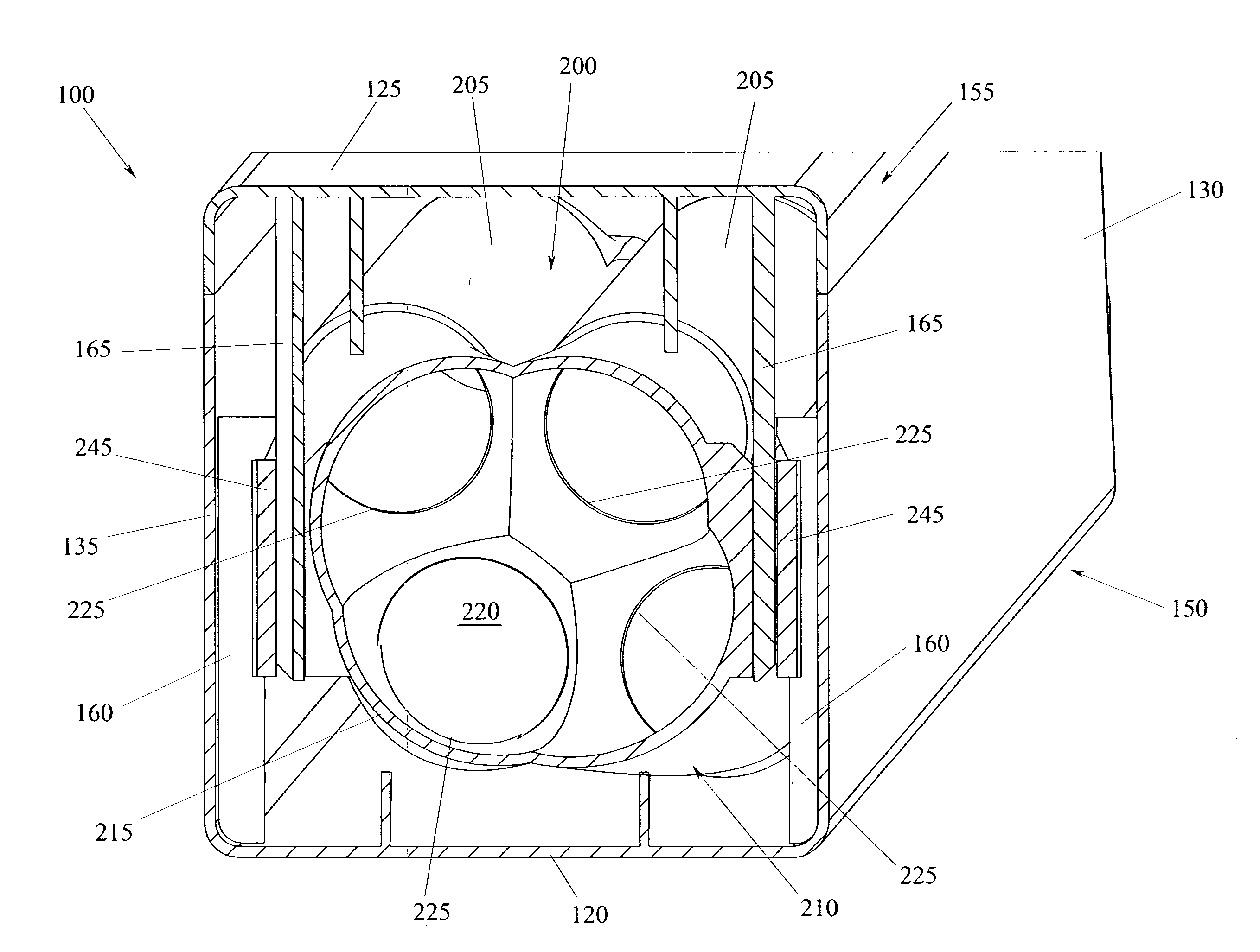
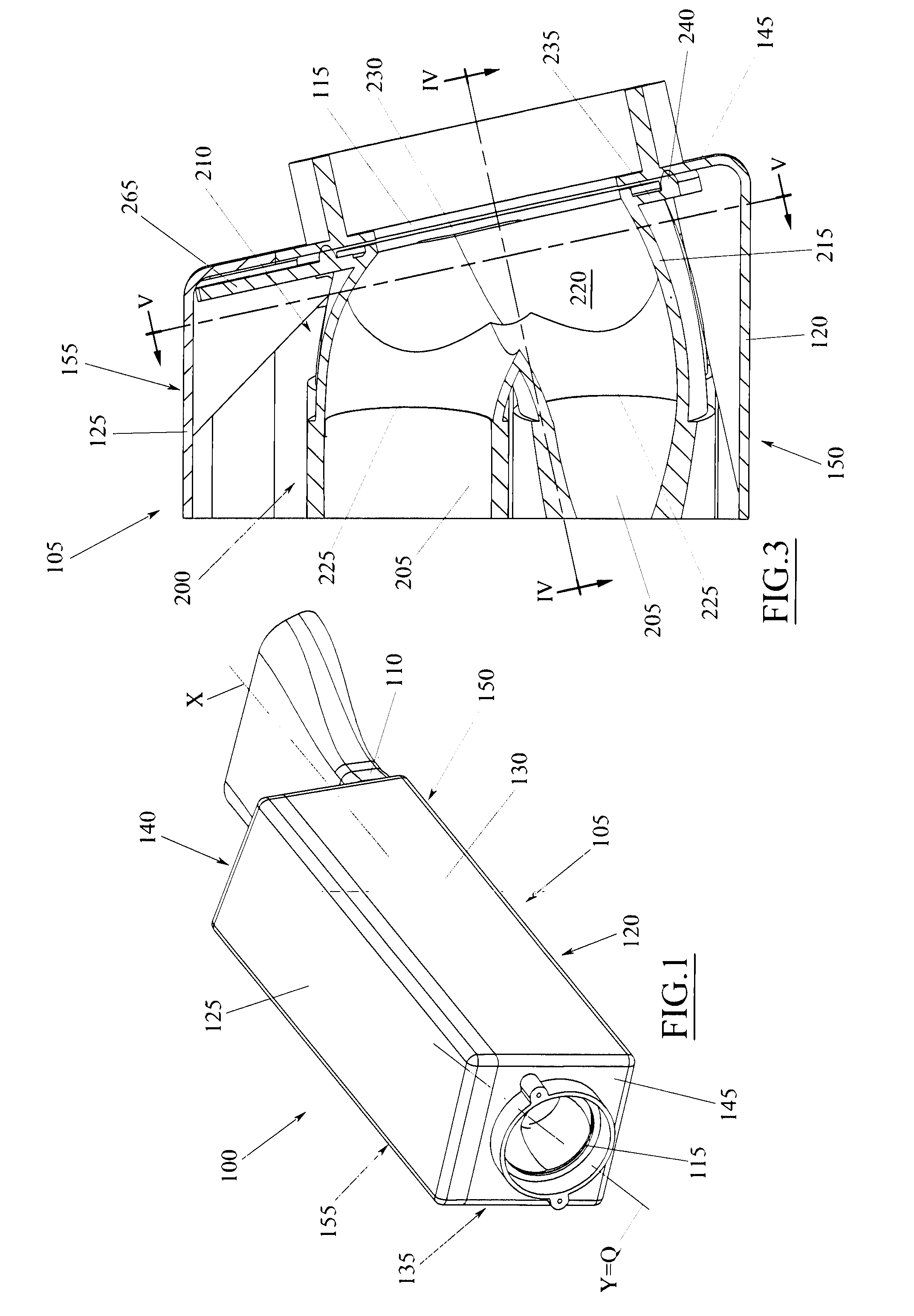
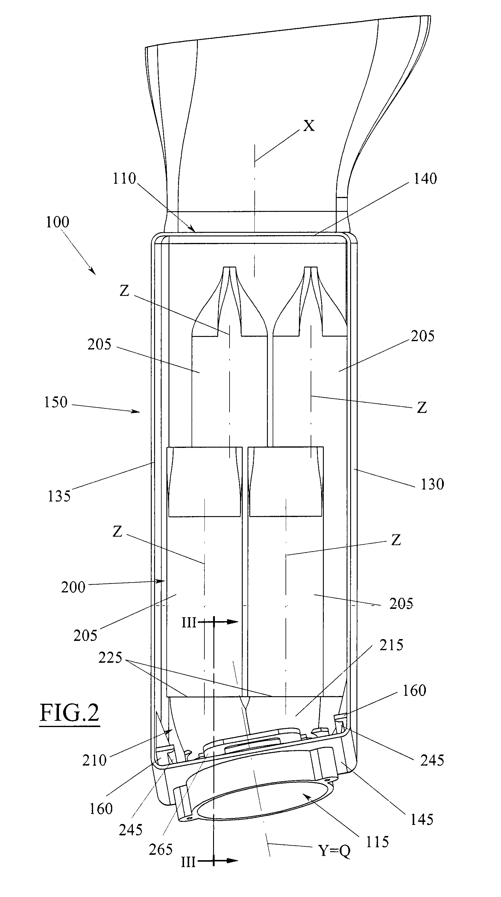
[0053]A filtering assembly 100, adapted to purify an airflow from the solid particles possibly present in suspension is illustrated in FIG. 1. More in particular, the filtering assembly 100 is intended to be positioned along an intake conduit of an internal combustion engine, so as to filter the comburent air that is suctioned into the combustion chambers of the engine.

[0054]The filtering assembly 100 comprises an outer casing 105, conventionally referred to as filter box, which may be generally made of plastic material. The outer casing 105 delimits an internal volume and it is provided with an inlet 110 for the air to be filtered and an outlet 115 for the filtered air, both communicating with said internal volume. The inlet 110 is intended to be in communication with the external environment, while the outlet 115 is adapted to be in communication with the engine combustion chambers, usually through an intake manifold.

[0055]The outer casing 105 is generally polyhedron-shaped, an ex...


PUM

PropertyMeasurementUnit
flexibleaaaaaaaaaa
volumeaaaaaaaaaa
tubular shapeaaaaaaaaaa

Abstract

A manifold element (210) for a filtering cartridge (200) comprising a shaped shell (215) provided with an internal volume (220) and a plurality of access ports (225, 230) communicating with said internal volume, among which a plurality of first access ports (225) and at least one second access port (230), wherein each of said first access ports (225) is adapted to be coupled with a respective filtering material element (205) so as to support it and be occluded thereby.

Description

TECHNICAL FIELD[0001]The present invention generally refers to filtering fluids, especially the filtration of motor vehicle fluids, in particular including the filtration of air that is taken in by an internal combustion engine.BACKGROUND ART[0002]As known, the air taken in by an internal combustion engine is usually subjected to a filtration stage aimed at purifying it from the solid particles in suspension, typically dusts of various types, to prevent the latter from reaching the engine combustion chambers. This filtration stage typically occurs by means of a special filtering assembly, which is positioned along the intake conduit of the internal combustion engine, upstream of the intake manifold and of the turbocharger if present.[0003]The filtering assembly schematically comprises an outer casing, usually referred to as filter box, which is provided with an inlet for the air to be filtered and an outlet for the filtered air, and a filtering cartridge received within said filter ...

Claims


Application Information

Patent Timeline
Patent Type & Authority Applications(United States)
IPC IPC(8): F02M35/104
CPCF02M35/104B01D46/0005B01D46/2411B01D46/2414B01D46/4227B01D2265/028B01D2279/60F02M35/10334F02M35/0201F02M35/02416F02M35/02483F02M35/0215B01D46/58
Inventor GIRONDI, GIORGIO
Owner UFI FILTERS SPA
Why Eureka
Try Eureka