Method and apparatus for determining working stroke of cylinder of internal combustion engine

A technology of working stroke and internal combustion engine, applied in electrical control, mechanical equipment, engine control, etc., can solve problems such as the distribution of unworkable strokes

Pending Publication Date: 2020-05-29
ROBERT BOSCH GMBH
View PDF6 Cites 0 Cited by
  • Summary
  • Abstract
  • Description
  • Claims
  • Application Information

AI Technical Summary

Problems solved by technology

However, since the crankshaft carries out two revolutions within one working cycle, it is not possible to unambiguously assign the working stroke to the detected position angle according to the description of the position angle of the crankshaft.

Method used


Image

  • Method and apparatus for determining working stroke of cylinder of internal combustion engine
  • Method and apparatus for determining working stroke of cylinder of internal combustion engine
  • Method and apparatus for determining working stroke of cylinder of internal combustion engine

Examples


Embodiment Construction

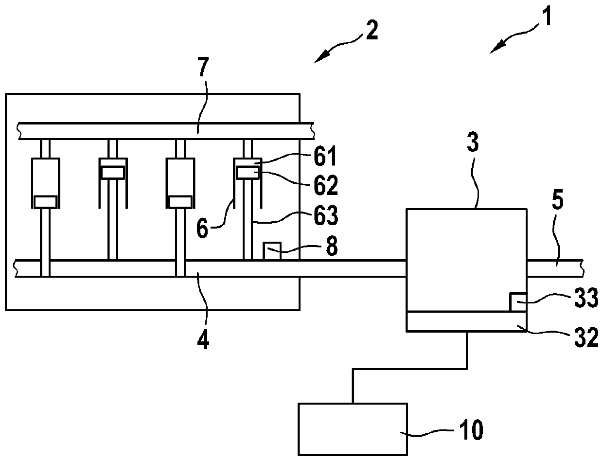
[0029] figure 1 A motor system 1 with a hybrid drive having an internal combustion engine 2 and an electric drive 3 is shown schematically. Internal combustion engine 2 includes a crankshaft 4 which is mechanically coupled to an electric drive 3 for providing a common drive torque via an output shaft 5 . It can be directly coupled to the output shaft via a clutch, belt or the like.

[0030] The drive torque results as a sum of the motor torque of internal combustion engine 2 and the electric drive torque of electric drive 3 .

[0031] The crankshaft 4 is coupled to the cylinders 6 of the internal combustion engine 2 , each cylinder 6 having a combustion chamber 61 and a combustion chamber movable piston 62 . The piston is mechanically coupled to the crankshaft 4 via a connecting rod 63 in such a way that the up and down movement of the piston 62 is converted into a rotational movement of the crankshaft 4 .

[0032] A motor controller 10 is provided which operates the intern...


PUM


Abstract

The invention relates to a method for operating a hybrid drive system having an internal combustion engine (2) and an electric drive (3), the internal combustion engine (2) being operated on the basisof a crankshaft position angle and a phase distribution of the crankshaft position angle with respect to a working stroke of one or more cylinders (6) of the internal combustion engine (2). The method has the following steps for ascertaining a phase distribution with respect to a working stroke of the cylinder (6): performing (S4) a test injection of fuel with respect to a piston movement of a piston expanding a combustion chamber in the cylinder (6); ascertaining (S5) a variation curve of an electric actuating variable for the electric drive (3); determining (S6), for the cylinder (6), a phase distribution of a crankshaft position angle with respect to a combustion stroke when it is determined that the power consumption of the electric drive (3) is reduced as a result of the test injection.

Description

technical field [0001] The invention relates to an internal combustion engine, in particular an internal combustion engine operated in stroke mode, for which the valve operation is controlled by means of a camshaft. Furthermore, the invention relates to measures for detecting a working stroke of a cylinder of an internal combustion engine. Background technique [0002] A crankshaft position sensor is provided to detect the position angle of the crankshaft in the internal combustion engine. With a four-stroke motor, the crankshaft is mechanically coupled to the camshaft in such a way that the camshaft makes one revolution when the crankshaft makes two revolutions. This determined deceleration allows in principle to infer the phase of the camshaft from the position angle of the crankshaft. However, since the crankshaft performs two revolutions within one working cycle, it is not possible to unambiguously assign the working stroke to the detected position angle based on the d...

Claims


Application Information

Patent Timeline
IPC IPC(8): F02D41/00
CPCF02D41/009F02D41/0087F02D41/1497F02D2250/24F02D2041/0092F02D2041/2058
Inventor R.埃尔曼C.德林格M.海因策尔曼
Owner ROBERT BOSCH GMBH
Why Eureka
Try Eureka