Method for molding powder mold product

a powder mold and product technology, applied in the field of powder mold product molding, can solve the problems of significant iron loss, and achieve the effect of highly productive molding

Active Publication Date: 2014-08-21
SUMITOMO ELECTRIC SINTERED ALLOY LTD +1
View PDF4 Cites 7 Cited by
  • Summary
  • Abstract
  • Description
  • Claims
  • Application Information

AI Technical Summary

Benefits of technology

The present invention provides a method for molding powder mold products that results in highly productive and uniform quality.

Problems solved by technology

The technical problem addressed in this patent is the reduction of eddy-current loss and iron loss in magnetic components used in high-frequency applications, by using coated particles with an insulating layer to prevent damage to the soft magnetic powder during the manufacturing process. Additionally, the use of a lubricant during the molding process improves powder moldability and reduces friction between the mold assembly and the powder mold product, resulting in a powder mold product with excellent insulating characteristics that further reduces eddy-current loss and iron loss in the powder magnetic core.

Method used


Image

  • Method for molding powder mold product
  • Method for molding powder mold product
  • Method for molding powder mold product

Examples


first embodiment

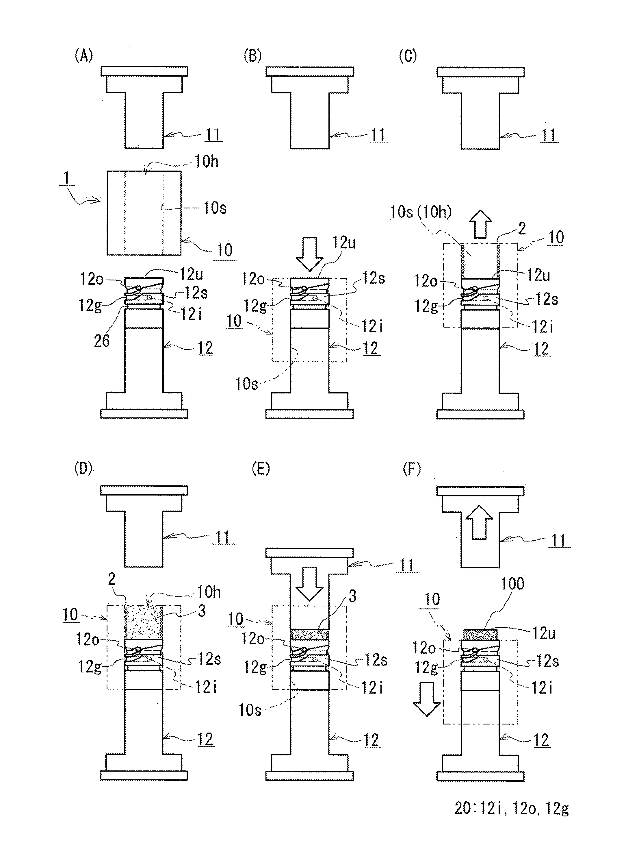
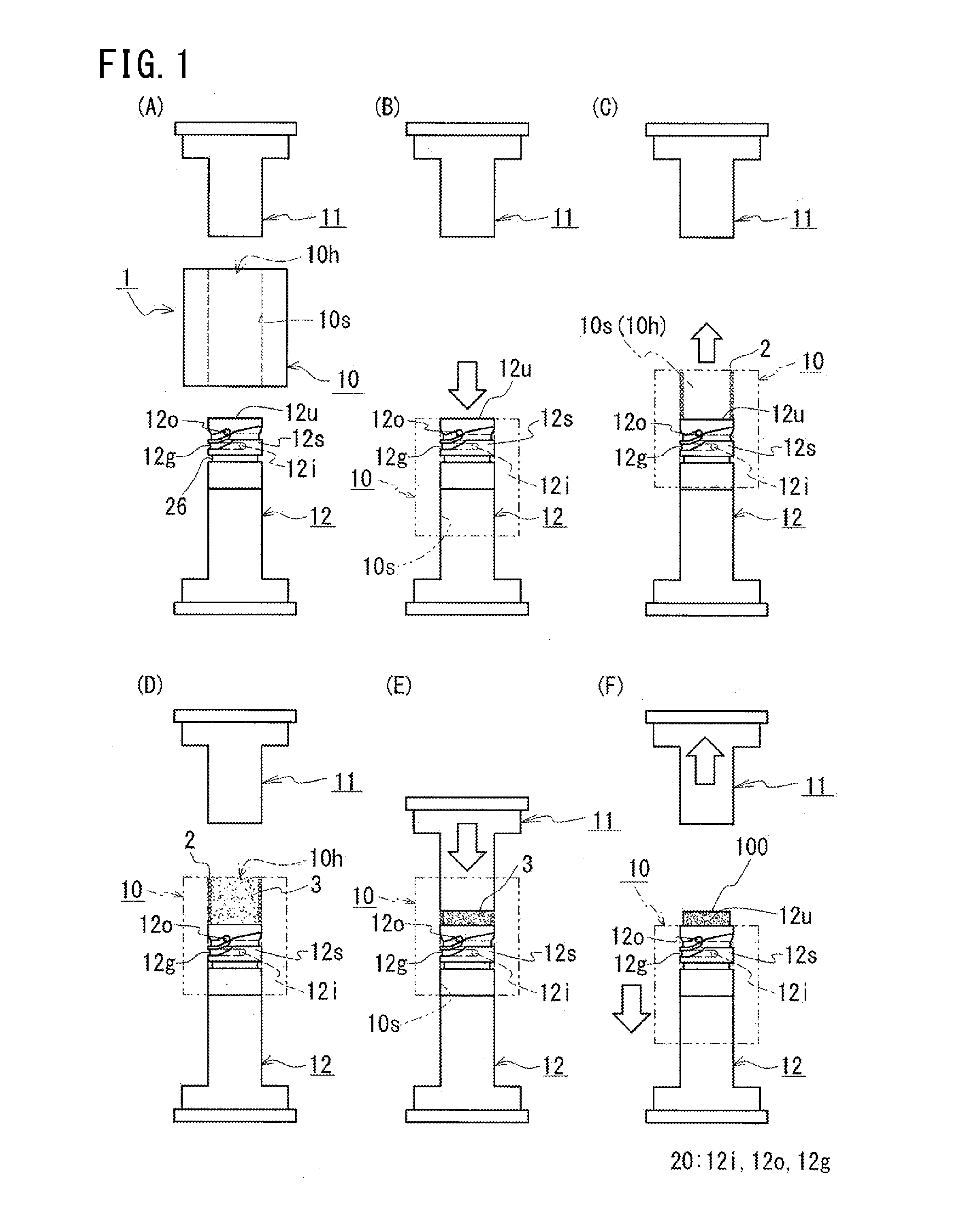
[0039]In the following, with reference to the drawings, a detailed description will be given of an exemplary manner of molding a powder magnetic core according to a method for molding a powder mold product of the present invention. In the description, firstly, a description will be given of a mold assembly used in the method for molding a powder mold product of the present invention. Subsequently, a description will be given of a mold assembly-use lubricant and raw material powder. Finally, a description will be given of the molding method. Note that, the method for molding a powder mold product of the present invention is not limited to molding of a powder magnetic core, and can be used for molding a non-magnetic powder mold product.

[0040][Mold Assembly]

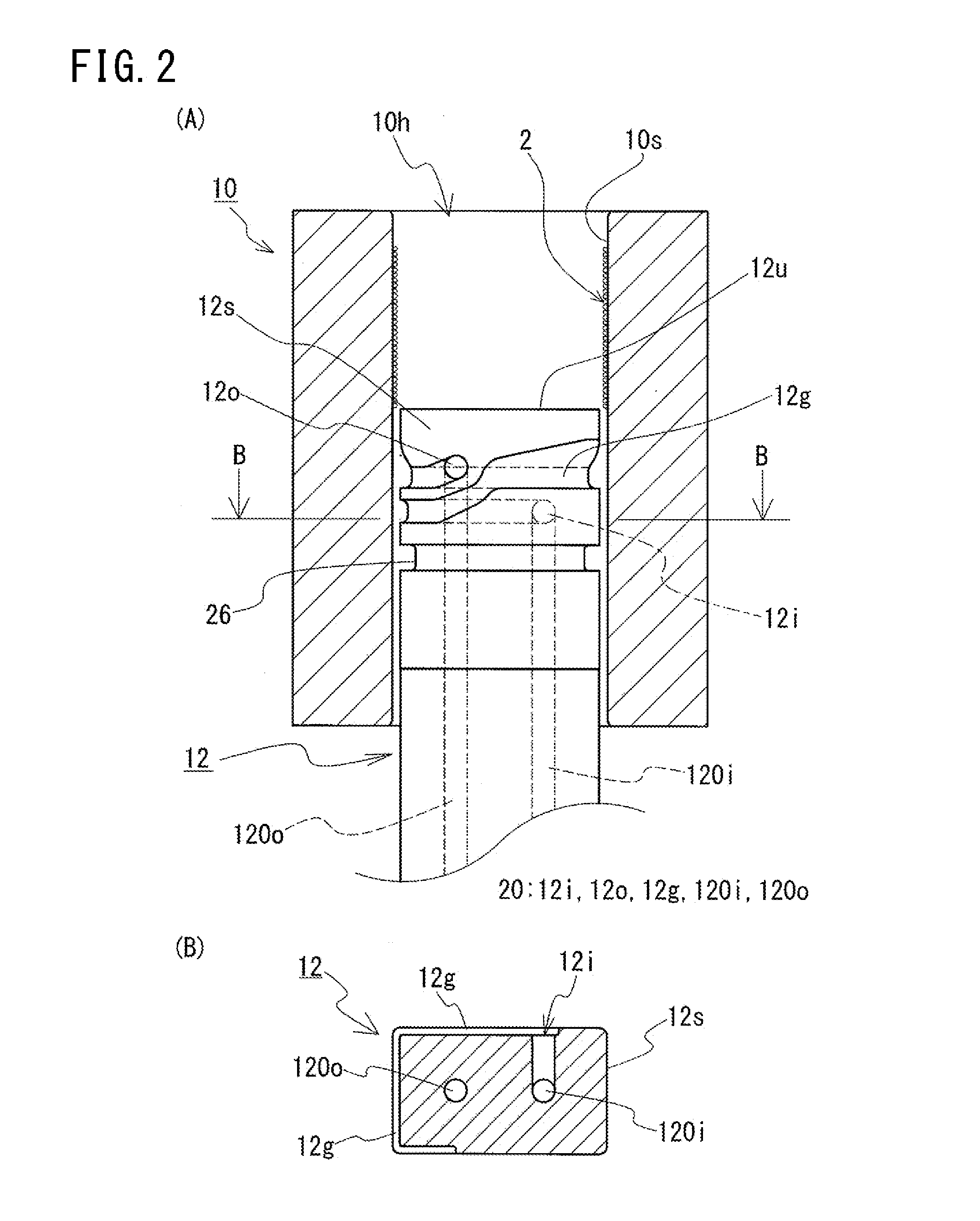
[0041]As a mold assembly to be used, for example, as shown in FIGS. 1 and 2, a mold assembly 1 that includes: a tubular die 10 having a quadrangular through hole 10h; and a pair of prism-shaped upper punch 11 and lower punch 12 remo...

second embodiment

[0107]In a second embodiment, a description will be given of a molding method of the present invention (the partial external lubrication) in which a mold assembly-use lubricant is applied to part of the inner circumferential face of the die. Before proceeding to the description, the mode of a mold assembly used herein will be described with reference to FIGS. 3(A) to (C). Note that, since the structures illustrated in FIG. 3 are identical to one another in that the supply port and the drain port are provided to the lower punch, only the lower punch is shown in FIG. 3.

[0108]In a lower punch 12A shown in FIG. 3(A), both the supply port 12i and the drain port 12o are formed on the face on the near side in the drawing, and the supply port 12i and the drain port 12o are displaced from each other in both the circumferential direction and the axial direction of the lower punch 12A. Accordingly, the circulative groove 12g connecting between the supply port 12i and the drain port 12o extends...


PUM

PropertyMeasurementUnit
Timeaaaaaaaaaa
Soft magnetismaaaaaaaaaa

Abstract

The present invention relates to a method for molding a powder mold product according to which a powder mold product of uniform quality can be molded with excellent productivity. The present invention includes the steps of: preparing raw material powder 3 (a preparing step); interposing a mold assembly-use lubricant between an outer circumferential face 12s of a first punch (a lower punch 12) and an inner circumferential face 10s of a die 10, the lower punch 12 and the die 10 in this state being relatively shifted to apply the mold assembly-use lubricant to the inner circumferential face 10s of the die 10 (an applying step); and packing the raw material powder 3 into a cavity, a powder mold product 100 being molded by the raw material powder 3 being pressed (a molding step). In the applying step, while the mold assembly-use lubricant is discharged from a supply port 12i provided to the lower punch 12 and the discharged mold assembly-use lubricant is collected from a drain port 12o provided to the lower punch 12, the mold assembly-use lubricant is applied to the inner circumferential face 10s of the die 10.

Description


Claims


Application Information

Patent Timeline
Owner SUMITOMO ELECTRIC SINTERED ALLOY LTD
Why Eureka
Try Eureka