Liquid Ejecting Head Unit and Liquid Ejecting Apparatus
a liquid ejecting head and liquid ejecting technology, applied in printing and other directions, can solve the problems of inevitably increasing the overall size of the liquid ejecting head unit, and achieve the effects of reducing the size, suppressing the thermal impact, and improving printing performan
- Summary
- Abstract
- Description
- Claims
- Application Information
AI Technical Summary
Benefits of technology
Problems solved by technology
Method used
Image

Examples
first embodiment
Liquid Ejecting Apparatus
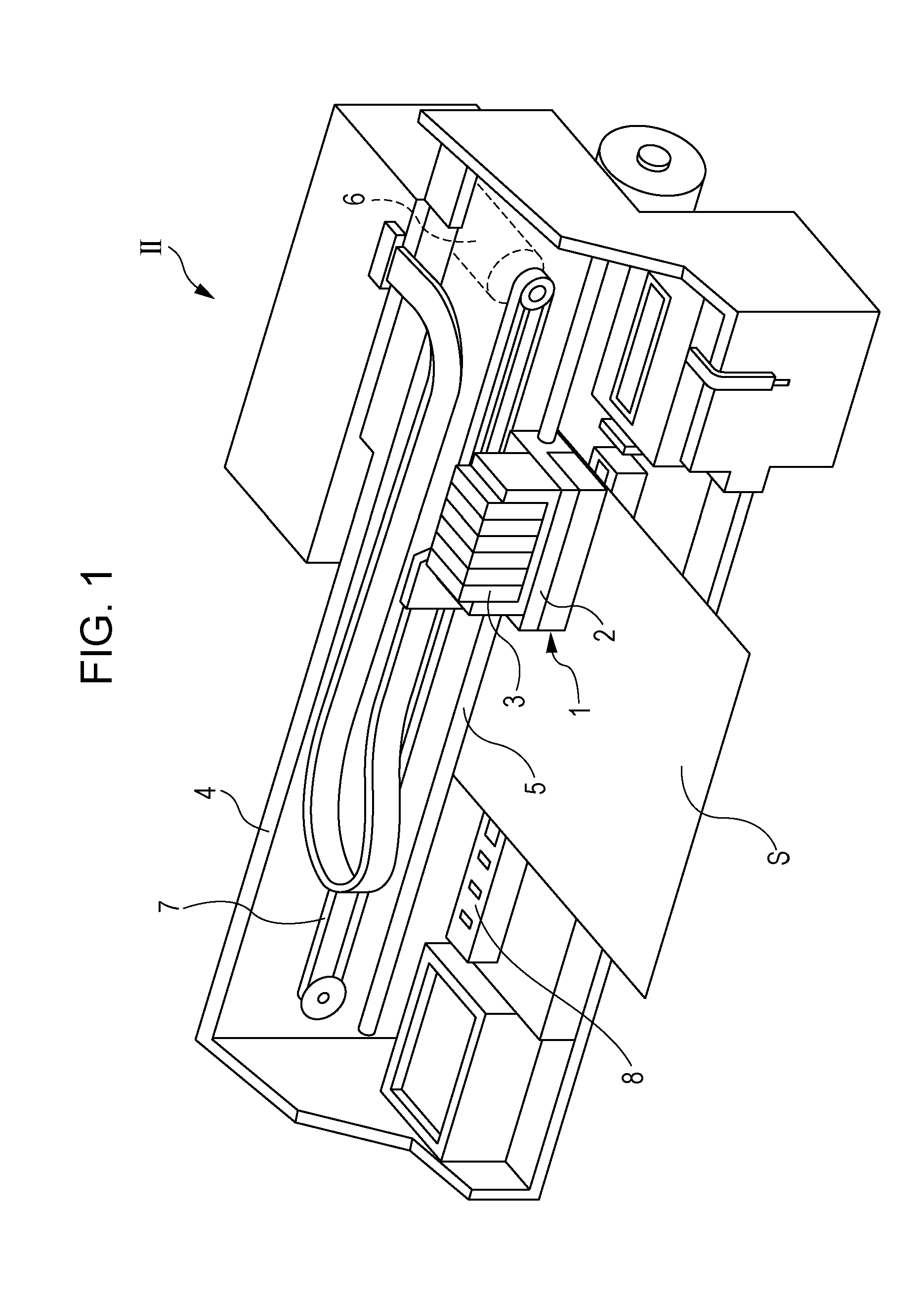
[0030]FIG. 1 is a perspective view showing an ink jet recording apparatus, exemplifying the liquid ejecting apparatus, according to a first embodiment of the invention. As shown in FIG. 1, the ink jet recording apparatus II includes an ink jet recording head module (hereinafter, simply head module) 1 that dispenses ink droplets, exemplifying the liquid ejecting head in the invention, fixed to a carriage 2.
[0031]A plurality of ink cartridges 3 each containing an ink are removably mounted on the head module 1. In this embodiment, the ink cartridges 3 respectively contain a plurality of different color inks, such as black (B), light black (LB), cyan (C), magenta (M), and yellow (Y).
[0032]The carriage 2 with the head module 1 mounted thereon is attached to a carriage shaft 5 provided in an apparatus main body 4, so as to move in the axial direction of the carriage shaft 5. The carriage 2 is driven to move along the carriage shaft 5 by a driving force of a drivin...
second embodiment
[0070]A second embodiment of the invention represents a head unit employed in a line-type ink jet recording apparatus (hereinafter, line recording apparatus).
[0071]A head unit IA according to this embodiment is for use in the line recording apparatus IIA, unlike the head unit according to the first embodiment. More specifically, while the ink jet recording apparatus II according to the first embodiment is configured to move the head module 1 mounted on the carriage 2 in the main scanning direction, the line recording apparatus IIA according to this embodiment performs the printing by moving the recording medium S such as a paper sheet in the main scanning direction, with a head module 1A fixed.
[0072]FIG. 6 illustrates an example of the line recording apparatus configured as above.
[0073]As shown in FIG. 6, the line recording apparatus IIA according to this embodiment performs the printing by transporting the recording medium S such as a paper sheet, which is the target of ejection, w...
third embodiment
[0092]A third embodiment represents the head unit IA according to the second embodiment, in which the housings 40A are substituted with housings 40B.
[0093]As shown in FIGS. 9 and 10, a head unit IB according to this embodiment includes two housings 40B provided in common for the two nozzle rows 301B located in an outer region of the communication plate 15B. In addition, a housing 40C is provided in common for the four nozzle rows 301C located in an inner region of the communication plate 15B. Thus, the head unit IB includes two housings 40B and one housing 40C. In this embodiment, the housings 40B and 40C are disposed to cover a plurality of nozzle rows.
[0094]In the housings 40B, 40C according to this embodiment, manifolds 100B, 100C are each provided in common for a plurality of nozzle rows. The ink of the same color is introduced in one manifold in this embodiment, and therefore the housings 40B, 40C include a single manifold 100B, 100C, respectively. The housings 40B, 40C each in...
PUM
 Abstract
Description
Claims
Application Information
 - R&D
- Intellectual Property
- Life Sciences
- Materials
- Tech Scout
- Unparalleled Data Quality
- Higher Quality Content
- 60% Fewer Hallucinations
Browse by: Latest US Patents, China's latest patents, Technical Efficacy Thesaurus, Application Domain, Technology Topic, Popular Technical Reports.
© 2025 PatSnap. All rights reserved.Legal|Privacy policy|Modern Slavery Act Transparency Statement|Sitemap|About US| Contact US: help@patsnap.com