Method of making an ink-jet recording head

a technology of inkjet recording and recording head, which is applied in the direction of metal-working apparatus, ohmic resistance heating, printing, etc., can solve the problems of inability to perform recordings of good quality, inability to perform recordings, and inability to achieve recordings. good quality, the effect of preventing heat influen

Inactive Publication Date: 2003-04-22
CANON KK
View PDF6 Cites 4 Cited by
  • Summary
  • Abstract
  • Description
  • Claims
  • Application Information

AI Technical Summary

Benefits of technology

The present invention is carried out to solve above-mentioned problems. An object of the present invention is to obtain the stagnant ink free and high reliable ink-jet head by removing completely by-products such as carbon deposits etc. generated during the laser fabrication and by preventing the heat influence, defects or foreign particles on the orifice plates, particularly around ejecting ports. Other object of the present invention is to improve printing quality of the ink-jet recordings.

Problems solved by technology

However, in the ink-jet recording head manufactured by the above-mentioned method, the resin film is decomposed by the laser light and part of the decomposed products deposit around ejecting ports on the front side of the orifice plate or on the back side of it, for example, as debris(carbon layer), when the excimer laser light is radiated to remove the resin from the spots where ejecting ports are to be fabricated.
However, in the ink-jet recording head where the orifice fabrication is made, such stagnant ink often exists at portions where above-mentioned deposits exist.
Due to the stagnant ink, flying trajectories of liquid droplets are not stable and therefore recordings of good quality can not be performed.
When such stagnant ink grows large, ejection of ink droplets becomes impossible and sometimes such stagnation leads to disorders that recordings become impossible.
In addition, such stagnant ink is sometimes formed by heat influence from the laser radiation and fabrication defects during connecting process of the orifice plate to the top board or deposition of foreign particles.

Method used


Image

  • Method of making an ink-jet recording head
  • Method of making an ink-jet recording head
  • Method of making an ink-jet recording head

Examples


embodiment 1

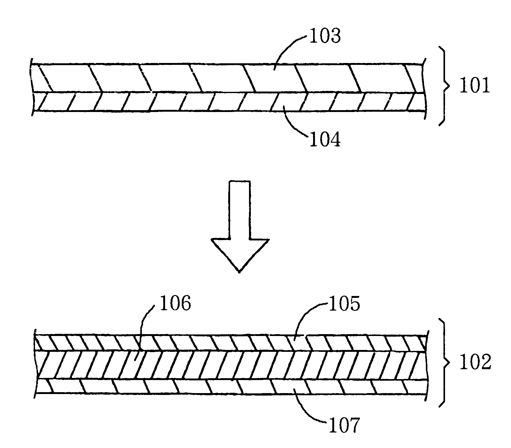
In FIG. 1 an illustration of an orifice plate in the embodiment 1 which explains characteristic features of the present invention is shown. In the figure a numeral character 101 represents a by-product removing tape and 103 represents a sheet member, a base plate for the removing tape 101. In the present embodiment polyethylene terephthalate film(referred to as PET film hereunder) is employed as the sheet member. An adhesive layer 104 which enables the sheet member 103 to be peeled off from the orifice plate, is applied on one side of the PET film 103, thus a by-product removing tape 101 is constituted.

The adhesive layer 104, in the present embodiment for example, is formed by applying 5 micrometer thick acrylic resin adhesive on the PET film 103. An orifice plate 102 is constituted by applying a water-repellent layer 105 on the front surface of 106 representing a plate member which employs polyimide film (referred to as PI film hereunder) used as a base plate for the orifice plate,...

embodiment 2

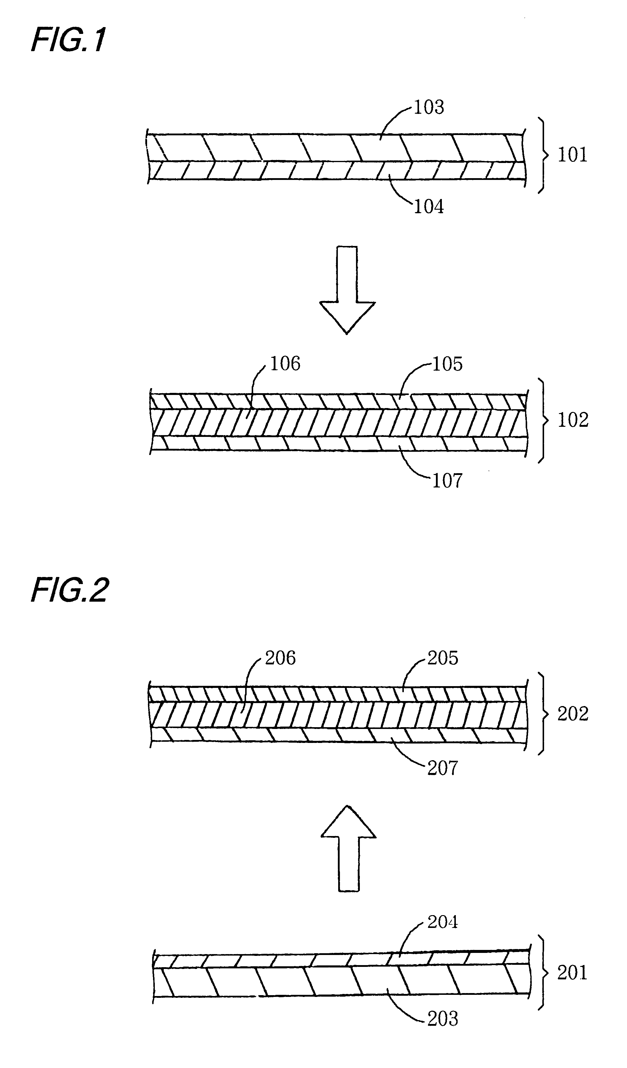
FIG. 2 illustrates embodiment 2 where the present invention is applied. In FIG. 2 a numeral character 201 represents a by-product removing tape and 203 represents a plate member made from poly(ether ether ketone) film(referred to as PEEK film hereunder) which is used as a substrate for the by-product removing tape 201. On one side of the PEEK film 203 an adhesive layer 204 is applied, thus the by-product removing tape 201 is constituted. In this embodiment the adhesive layer 204 is formed by applying 3 micrometer thick rubber adhesive.

An orifice plate 202 is constituted by applying a water-repellent layer 205 on one of the surfaces of 206 which represents a plate member made from polysulfone film(referred to as PSF film hereunder) used as a substrate, and by applying an adhesive layer 207 on the other surface. The water repellent layer 205 is formed by applying a water repellant "Cytop" (the trade name of the Asahi glass company) on the PSF film 206 and then by baking the film 206 a...

embodiment 3

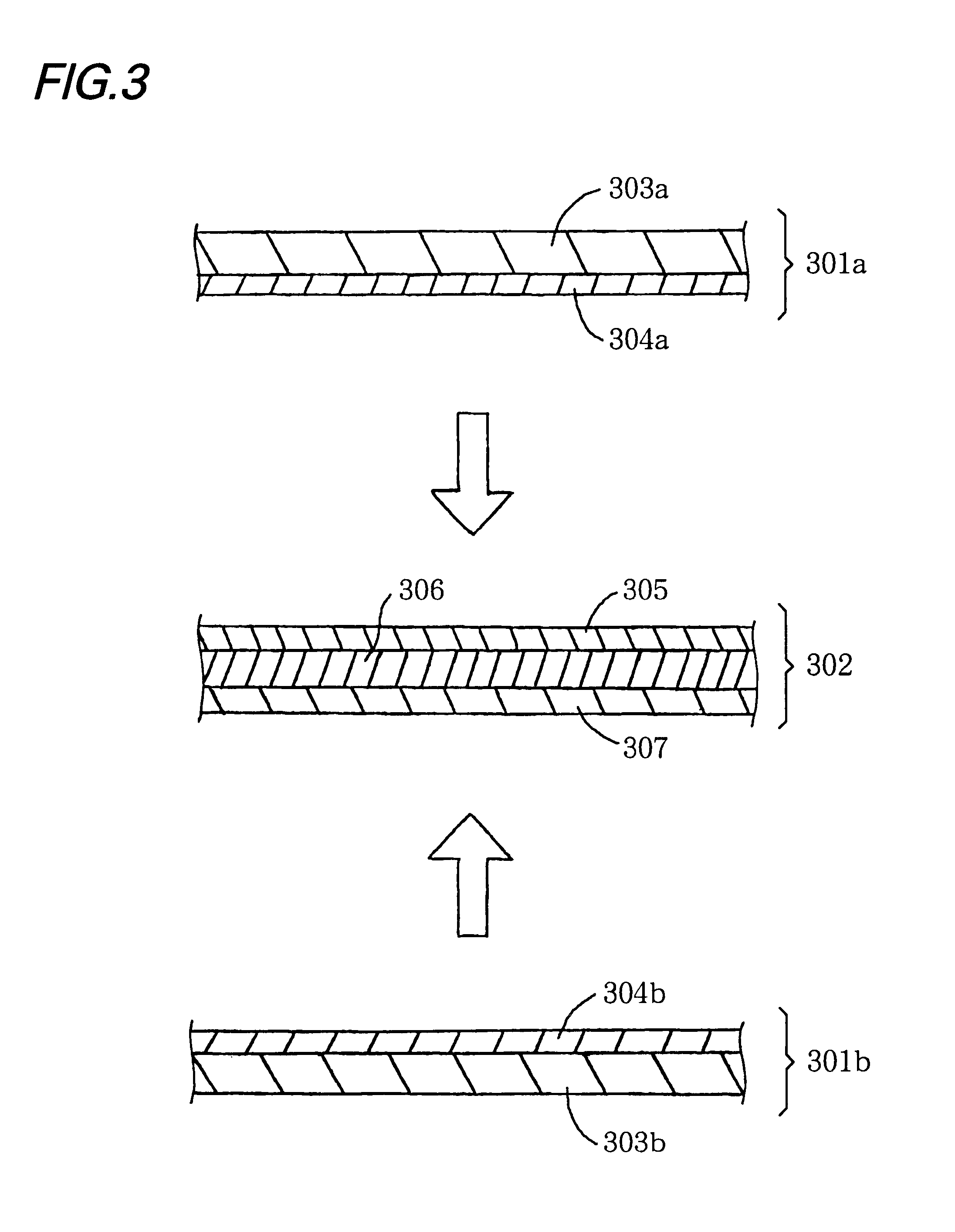
FIG. 3 illustrates embodiment 3 where the present invention is applied. In the FIG. 3 numeral characters 301a and b represent by-product removing tapes and 303a and b represent plate members made from poly(ether sulfone) film(referred to as PES film hereunder) which is used as substrates for the by-product removing tapes 301a and b. On one side of the PES film 303a and b adhesive layer 304a and b are applied, thus the by-product removing tapes 301a and b are constituted respectively. The adhesive layer 304a and b are formed by applying 3 micrometer thick acrylic resin adhesive.

An orifice plate 302 is constituted by applying a water-repellent layer 305 on one of the surfaces of 306 which represents a plate member made from polysulfone film (PSF film) used as a substrate, and by applying an adhesive layer 307 on the other surface of the PSF film respectively. The water repellent layer 305 ,is formed by applying a water repellant "Cytop"(the trade name of the Asahi glass company) on th...


PUM

PropertyMeasurementUnit
thickaaaaaaaaaa
thickaaaaaaaaaa
wave lengthaaaaaaaaaa

Abstract

The present invention provides a manufacturing method of an ink-jet recording head which does not form stagnant ink even at a high density and high speed recording and does not bear stagnant ink due to a heat influence during radiation of excima laser beam on ejecting ports(orifice) 706 and due to defects or deposited foreign particles during connecting the orifice 706 with a top board 102.In order to obtain such recording heads, before fabricating the ejecting ports 706 a by-product removing tape 101 is pasted capable of being peeled off, on eject port forming plate which is fabricated to an orifice plate 102, so as to increase adhesive property between the by-product removing tape and removed portion by the laser beam.

Description

1. Field of InventionThe present invention relates to an ink-jet recording head which has an ejecting port forming plate (often referred as orifice plate hereinafter) where ejecting ports are formed, and relates to a manufacturing method of the ink-jet recording head2. Brief Description of the Related ArtToday ultra-violet laser light etc., as one of the typical excimer laser light(beam) etc. are used for fabricating ejecting ports of above-mentioned type of the ink-jet recording head. Orifice fabrications have been done by radiating the excimer laser light on a side which leads to liquid paths, of surfaces of resin film, for example, a member for the orifice plate.However, in the ink-jet recording head manufactured by the above-mentioned method, the resin film is decomposed by the laser light and part of the decomposed products deposit around ejecting ports on the front side of the orifice plate or on the back side of it, for example, as debris(carbon layer), when the excimer laser...

Claims


Application Information

Patent Timeline
Patent Type & Authority Patents(United States)
IPC IPC(8): B41J2/16B41J2/135B41J2/05
CPCB41J2/162B41J2/1634Y10T29/49401Y10T29/49083
Inventor TATSUMI, JUNJI
Owner CANON KK
Why Eureka
Try Eureka