Ignition unit

a technology of ignition unit and housing, which is applied in the direction of combustion types, combustion processes, burners, etc., can solve the problems of complex assembly of fixing operations and make the assembly of an ignition unit extremely complex, and achieve the effects of reducing thermal influence on the main unit, improving the reliability of the ignition unit itself, and ensuring the safety of the main uni

Inactive Publication Date: 2005-02-24
NORITZ CORP
View PDF6 Cites 7 Cited by
  • Summary
  • Abstract
  • Description
  • Claims
  • Application Information

AI Technical Summary

Benefits of technology

[0015] In addition, it may be arranged such that the guide rail is provided with a concave groove which opens at a side surface of the guide rail and which extends in a straight line along the guide rail, and that an end edge of the clamp piece which extends in the insertion engagement direction is engaged into the concave groove. By performing an insertion engagement operation with the end edge of the clamp piece engaged into the concave groove of the guide rail, it becomes possible to mount the main unit onto the bracket in such a restricted state that there occurs no displacement with respect to all of the orthogonal triaxial direction. This makes it possible to more strongly and highly realize the unification of the main unit and the bracket.
[0016] Furthermore, it may be arranged such that the housing of the main unit is provided with two guide rails while on the other hand the bracket has a central clamp piece which is inserted between the two guide rails and two outer clamp pieces which are arranged outside the two guide rails respectively, and that the central clamp piece is arranged so that, when the main unit is mounted onto the bracket, the guide rails are clamped between the central clamp piece and each of the outer clamp pieces, with the central clamp piece spaced apart from the outer surface of the housing so as to define a space therebetween. In this case, it becomes possible for the central clamp piece to shield the housing's outer surface, with a layer of air intervened between the housing's outer surface and the central clamp piece. Accordingly, even when, with the combustion of the ignition target, radiation heat is received from the dividing wall of the ignition target to which the bracket is fixed, it becomes possible to suppress thermal influence on the main unit as much as possible by heat reflection by the central clamp piece and heat insulating action by the air layer. Because of this, the durability of the main unit whose housing contains therein the high voltage output part and so on is improved, thereby making it possible to improve the reliability of the ignition unit itself.
[0017] In the third place, it may be arranged such that the high voltage output terminal is accommodated in the inside of a tubular cover which projects from the housing of the main unit and which opens at a leading end thereof. As a result of such an arrangement, in the state in which the conductive connection between the high voltage output terminal and the high voltage input terminal is established, it becomes possible to avoid the possibility of occurrence of the leak of electricity caused by a spark leak from the sharp end of the high voltage output terminal or from the sharp end of the high voltage input terminal. Especially in the case where the dividing wall to which the bracket is attached fixedly is situated in the vicinity of the high voltage output terminal or the like placed in the aforesaid conductive connection state, the occurrence of such electricity leakage is avoided effectively.
[0018] Additionally, in the case where such a tubular cover is added, it may be arranged such that the high voltage input terminal is shaped like a rod while on the other hand the high voltage output terminal has a leading end opening which receives therein the rod-shaped high voltage input terminal by the insertion engagement of the main unit, and that an inner surface of the tubular cover is shaped like a funnel the diameter of which gradually decreases from a portion thereof which opens at a greater diameter than that of the leading end opening of the high voltage output terminal to the leading end opening of the high voltage output terminal. As a result of such arrangement, even when any one of the high voltage output and input terminals or both undergo a slight displacement in an insertion engagement operation of the main unit to the bracket, it is possible to provide guidance to a conductive connection position by guiding the high voltage input terminal along over the funnel-shaped internal surface of the tubular cover. This therefore makes it possible to ensure that the conductive connection of the high voltage output terminal and the high voltage input terminal is established without fail. Because of this, the process to the mutual conductive connection of the main unit-side high voltage output terminal and the spark plug-side high voltage input terminal is guided reliably in the insert engagement of the main unit into the bracket, thereby making it possible to ensure that the conductive connection is established without fail.

Problems solved by technology

In the third place, in the case of employing a technique in which the ignition electrode and the casing are not united together but are just connected together and they are individually fixed to the burner case or the like by screws or other fixing means, such fixing operations make the assembly of an ignition unit extremely complex.

Method used


Image

  • Ignition unit
  • Ignition unit
  • Ignition unit

Examples


Embodiment Construction

[0028] Hereinbelow, embodiments of the present invention will be described with reference to the drawings.

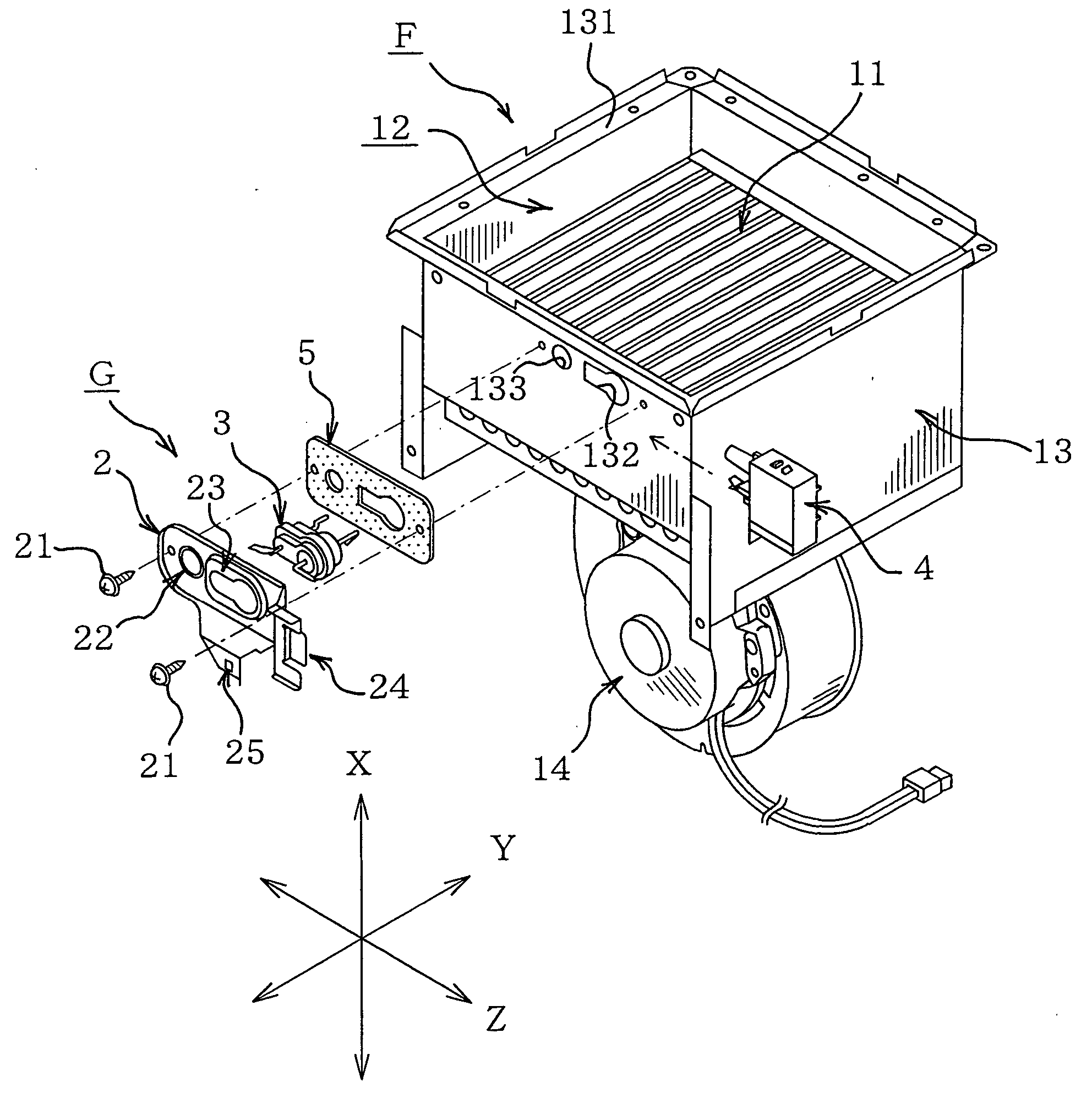
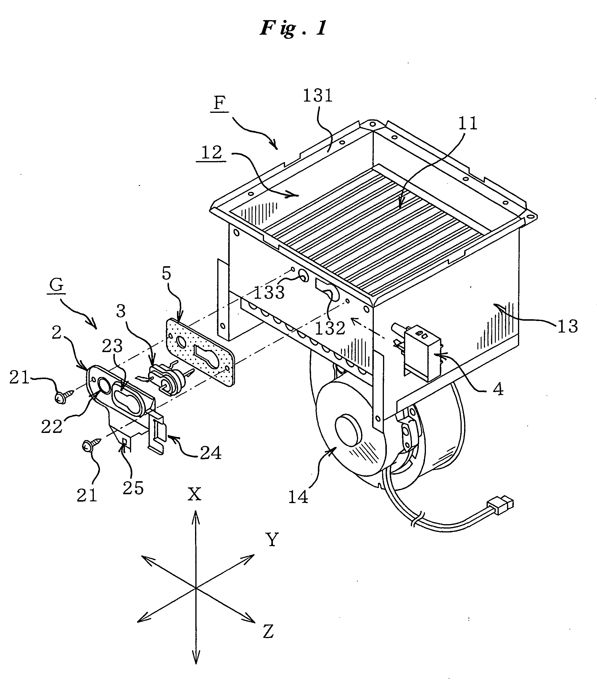
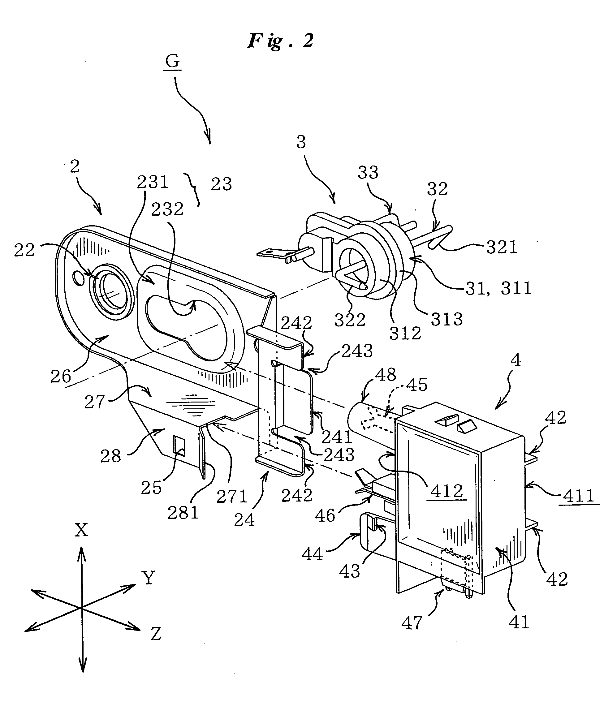
[0029] Referring to FIG. 1, there is shown an exploded perspective illustration of an ignition unit G of the present invention which is incorporated into a combustion system F for hot water supply equipment. This combustion system F is made up of: a combustion burner 11 formed by combustion tubes arrayed side by side in a plurality of rows; a burner case 13 which contains therein the combustion burner 11 to divisionally define a space for a combustion chamber 12 above the combustion burner 11; and an fan 14 which provides a supply of combustion air to the combustion burner 11. The combustion system F serves to heat water to a predetermined level of temperature by use of the combustion heat of the combustion burner 11 and supplies the hot water to a hot water tap or the like. More specifically, a storage water heater body (not shown in the figure) which houses therein for example...


PUM


Abstract

An ignition unit promotes the efficiency of assembly because connections on the high voltage output side and the ground side are completed by a single operation, when an ignition electrode part and a main unit are connected together directly. A guide rail of the main unit is insertion-engaged into a slit between clamp pieces of a bracket so that the main unit is mounted onto the bracket. With the insertion engagement, a high voltage output terminal receives therein a high voltage input terminal of a spark plug supported by the bracket, a plate terminal which is a part of the bracket is driven into a ground-side connection terminal, and a convex portion of a projected piece is engaged into an engagement hole, for positioning and slipping-off prevention.

Description

BACKGROUND OF THE INVENTION [0001] 1. Field of the Invention [0002] The present invention generally relates to an ignition unit for igniting the burner of a burning appliance (e.g., a water heater, a heating apparatus et cetera) which makes utilization of the combustion of liquid fuel (e.g., kerosene) or gas fuel (e.g., gas). This invention relates more particularly to an ignition unit which is configured such that fuel, blown out from the burner, is ignited by a spark discharge from an ignition electrode and is burned. [0003] 2. Description of the Related Art [0004] Such a type of ignition unit is called the “ignitor”. One such example of the ignition unit of this type has been known in the art, which is comprised of an ignition electrode capable of generation of spark discharges and a transformer mounted in the inside of a casing. The transformer receives a supply of electric power from a commercial power source and then voltage-transforms it into a high voltage for discharge at t...

Claims


Application Information

Patent Timeline
Patent Type & Authority Applications(United States)
IPC IPC(8): F23Q3/00
CPCF23Q3/008
Inventor SUYAMA, HIDEYAYOSHIMOTO, ATSUSHIUEHARA, KOZOKUMON, MASAAKINAKAI, SATOSHIKAWAUCHI, KAZUYASAIKI, TAKUJIKIMURA, SHINGOTANAKA, NAOMI
Owner NORITZ CORP
Why Eureka
Try Eureka