
Imaging apparatus

a technology of image processing and image processing, applied in the direction of color television details, color signal processing circuits, electrical apparatus, etc., can solve the problems of inability to accurately calculate wb gain, inability to perform thinning-reading susceptible to the like, and inability to calculate highly accurate wb gain having reduced adverse effects of color mixture, etc., to achieve the smallest amount of operation for calculating white balance gain, the effect of improving the reproducibility accuracy of a demo

Inactive Publication Date: 2014-08-21
FUJIFILM CORP
View PDF3 Cites 15 Cited by
  • Summary
  • Abstract
  • Description
  • Claims
  • Application Information

AI Technical Summary

Benefits of technology

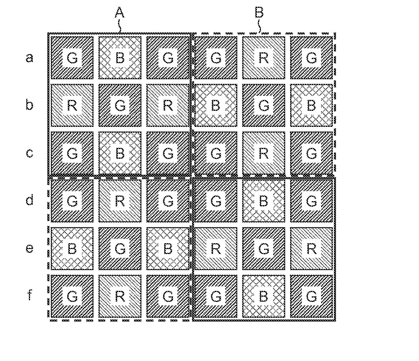
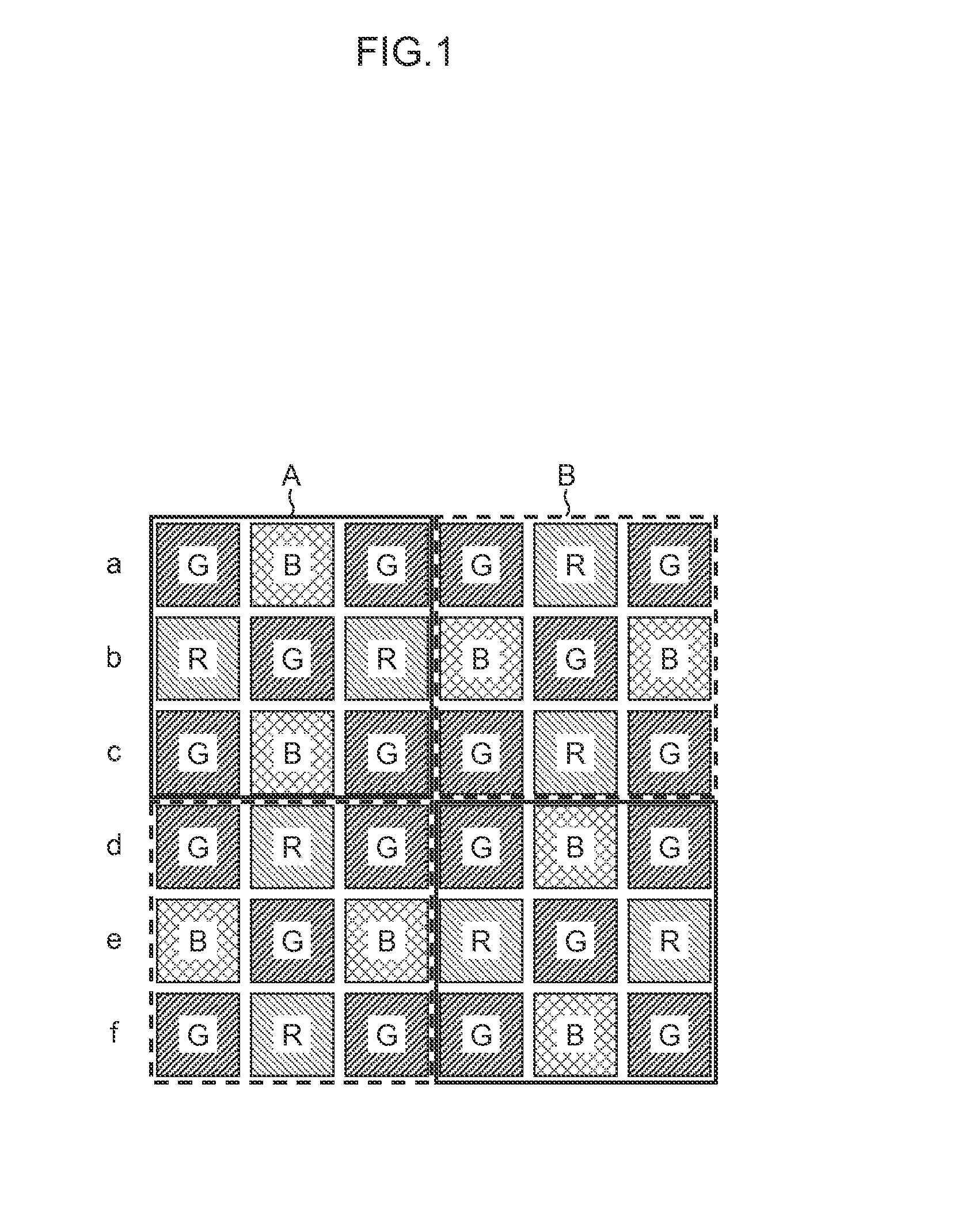
The present invention provides an imaging apparatus and image processing method that can quickly and accurately calculate the white balance gain while considering the effects of noise and color mixture between adjacent pixels. This allows for a highly accurate white balance correction to be performed quickly. The invention uses an image pickup device with a specific color filter array where the ratios of the numbers of color filters of three primary colors are different between lines. White balance gains are calculated on the basis of the color signals corresponding to color filters of the respective colors on lines with relatively even ratios of the numbers of color filters of the three primary colors. This ensures highly accurate white balance gains with small adverse effects of noise. In cases where there is a high degree of color mixture, the white balance gains are calculated on the basis of the color signals on lines with a small degree of color mixture (lines having uneven ratios of the numbers of color filters of the three primary colors). Conversely, in cases where there is a low degree of color mixture, the white balance gains are calculated on the basis of the color signals on lines with small adverse effects of noise (lines with relatively even ratios of the numbers of color filters of the three primary colors). This ensures highly accurate white balance gains and a quick and efficient white balance correction.

Problems solved by technology

There is a problem in that if a WB gain is calculated on the basis of RGB color signals with a high degree of color mixture, the WB gain cannot be accurately calculated.
Even if thinning-reading on lines is appropriately changed for calculating a WB gain, thinning-reading resistant to adverse effects of color mixture, thinning-reading susceptible to adverse effects of color mixture and the like cannot be performed.
Thus, a highly accurate WB gain having reduced adverse effects of color mixture cannot be calculated.

Method used


Image

  • Imaging apparatus
  • Imaging apparatus
  • Imaging apparatus

Examples


third embodiment

[0154]FIG. 12 is a flowchart showing a third embodiment of a method of calculating WB gains. The same step numerals are assigned to portions common to those of the first embodiment shown in FIG. 9. The detailed description thereof is omitted.

[0155]The CPU 40 calculates the brightness of a subject (imaging EV value) from the integrated values input from the AE detector 44 upon half-pressing of the shutter release button, determines an imaging (exposure) condition including the combination of an f-number, a shutter speed and an imaging sensitivity (ISO sensitivity) on the basis of the imaging EV value, and performs exposure control according to the exposure condition determined upon actual imaging.

[0156]If the brightness of the subject is high, the imaging sensitivity is set to be low, and exposure control is performed according to the f-number and the shutter speed. In contrast, if the brightness of the subject is low and a sufficient amount of signals cannot be acquired only with th...

fourth embodiment

[0159]FIG. 13 is a flowchart showing a fourth embodiment of a method of calculating WB gains, and represents a modified example of the third embodiment shown in FIG. 12. The same step numerals are assigned to portions common to those of the third embodiment shown in FIG. 12. The detailed description thereof is omitted.

[0160]In the fourth embodiment shown in FIG. 13, processes on and after determination that the imaging sensitivity exceeds the prescribed threshold (“No” in step S40) are different from those of the third embodiment.

[0161]That is, if it is determined that the imaging sensitivity exceeds the prescribed threshold in step S40 ((in the case of “No”), it is subsequently determined whether priority is given to the operation speed or not (step S50).

[0162]For instance, if a consecutive imaging mode is set as an imaging mode and each of consecutively taken images are required to be processed at high speed, it is determined that priority is given to the operation speed.

[0163]If ...

first embodiment

[0166]Not only a signal component corresponding to the intensity of incident light but also an offset component caused by dark current and the like are superimposed on the RGB color signals output from the image pickup device 1. In the cases of high sensitivity, high temperature, and long time exposure, a step tends to occur in an offset component owing to a dark current component in the pixels.

[0167]FIG. 14 is a diagram showing the case where a step (black level step) occurs in an offset in each of RGB colors.

[0168]To address this, highly accurate WB gains are calculated by calculating color information (R / G and B / G) in consideration of this offset step.

[0169]That is, the RGB integrator 246 shown in FIG. 8 calculates offset values Roffset, Goffset and Boffset for the respective RGB colors. These offset values Roffset, Goffset and Boffset are calculated by integrating signals that are in a light shield region (optical black portion: OB portion) at a peripheral portion of the image p...


PUM


Abstract

White balance correction is performed on RGB color signals output from an image pickup device that includes a particular color filter array in which RGB color filters are arranged on respective lines and the ratios of the numbers of RGB color filters are different between the lines. For calculation of WB gains used for the white balance correction, not all the pixels of the image pickup device but prescribed lines are used to thinning-read. The WB gains are calculated based on color signals on the thinning-read prescribed lines. As the prescribed lines to be thinning-read, lines having a small degree of color mixture are selected under an imaging condition (a lens f-number and a zoom position) with a high degree of color mixture; lines having relatively even ratios of the numbers of RGB color filters are selected under an imaging condition having a low degree of color mixture.

Description

CROSS-REFERENCE TO RELATED APPLICATIONS[0001]This application is a continuation application and claims the priority benefit under 35 U.S.C. §120 of PCT Application No. PCT / JP2012 / 077302 filed on Oct. 23, 2012 which application designates the U.S., and also claims the priority benefit under 35 U.S.C. §119 of Japanese Patent Application No. 2011-239321 filed on Oct. 31, 2011, which applications are all hereby incorporated by reference in their entireties.BACKGROUND OF THE INVENTION[0002]1. Field of the Invention[0003]The present invention relates to an imaging apparatus and an image processing method and, in particular, to technologies for speedily and accurately calculating a white balance gain.[0004]2. Description of the Related Art[0005]Japanese Patent Application Laid-Open No. 2007-295300 (hereinafter referred to as PTL 1) discloses an imaging apparatus that calculates a white balance gain (WB gain) on the basis of an image thinned (extracted) from an image in the entire region of...

Claims


Application Information

Patent Timeline
Patent Type & Authority Applications(United States)
IPC IPC(8): H04N9/73H04N23/12
CPCH04N9/73H04N2209/045H04N23/84H04N25/134H04N23/88
Inventor FURUTA, YOSHINORI
Owner FUJIFILM CORP
Learn More