Heat dissipation device and manufacturing method thereof

a heat dissipation device and manufacturing method technology, applied in the direction of indirect heat exchangers, lighting and heating apparatus, semiconductor/solid-state device details, etc., can solve the problems of affecting the smooth flow of working fluid, affecting the and unable to tightly attach the heat dissipation device to the heat generation component. , to achieve the effect of longer life of the heat dissipation devi

Active Publication Date: 2014-08-28
ASIA VITAL COMPONENTS SHENZHEN CO LTD
View PDF17 Cites 2 Cited by
  • Summary
  • Abstract
  • Description
  • Claims
  • Application Information

AI Technical Summary

Benefits of technology

[0012]A primary object of the present invention is to provide a heat dissipation device, which can increase assembling tightness to avoid thermal resistance.
[0013]A further object of the present invention is to provide a manufacturing method of a heat dissipation device, which can increase assembling tightness to avoid thermal resistance.
[0020]According to the heat dissipation device and the manufacturing method thereof, the heat dissipation device can be more tightly attached to a heat source so as to avoid thermal resistance. Moreover, the fixing hole is formed on the main body without damaging the chamber of the main body. Therefore, the chamber is kept vacuumed and airtight to avoid leakage of working fluid. Accordingly, the present invention has the following advantages:
[0022]2. The working fluid is prevented from leaking out of the chamber.
[0023]3. The lifetime of the heat dissipation device is longer.

Problems solved by technology

Therefore, after affixed to the substrate, the heat spreader can hardly tightly attach to the heat generation component.
However, after the copper pillars penetrate through the chamber of the heat spreader, the chamber is no more vacuumed and will lose its airtightness.
Moreover, the copper pillars that pass through the chamber will interrupt the flowing path of the working fluid contained in the chamber and hinder the working fluid from smoothly flowing.
This will deteriorate heat transfer efficiency or even cause leakage of the working fluid.
Under such circumstance, the heat spreader will lose its heat transfer effect.
This lowers the heat transfer efficiency.
1. The conventional heat spreader is likely to have the problem of thermal resistance.
2. The heat dissipation area of the conventional heat spreader is smaller.
3. The heat transfer efficiency of the conventional heat spreader is lowered.

Method used


Image

  • Heat dissipation device and manufacturing method thereof
  • Heat dissipation device and manufacturing method thereof
  • Heat dissipation device and manufacturing method thereof

Examples


Embodiment Construction

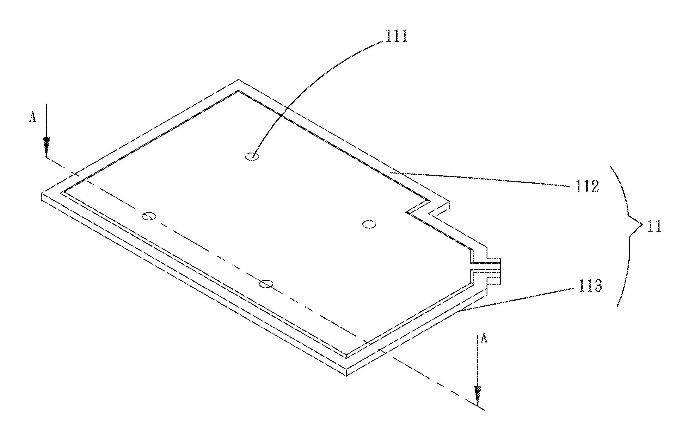
[0042]Please refer to FIGS. 2, 3 and 4. FIG. 2 is a perspective exploded view of a first embodiment of the heat dissipation device of the present invention. FIG. 3 is a perspective assembled view of the first embodiment of the heat dissipation device of the present invention. FIG. 4 is a sectional view taken along line A-A of FIG. 3. According to the first embodiment, the heat dissipation device 1 of the present invention includes a main body 11 and at least one fixing hole 111.

[0043]The main body 11 has a first board body 112 and a second board body 113 corresponding to the first board body 112. The first and second board bodies 112, 113 are mated with each other to define a chamber 114. The chamber 114 has a first inner side 1141 and a second inner side 1142. A working fluid 115 and multiple support pillars 116 are disposed in the chamber 114. At least one capillary structure 117 is disposed on a surface of the chamber 114. Two ends of the support pillar 116 arc connected to the f...


PUM

PropertyMeasurementUnit
capillary structureaaaaaaaaaa
heat transfer efficiencyaaaaaaaaaa
sizeaaaaaaaaaa

Abstract

A heat dissipation device and a manufacturing method thereof. The heat dissipation device includes a main body and at least one fixing hole. The main body has a first board body and a second board body corresponding to the first board body. The first and second board bodies are mated with each other to define a chamber. A working fluid and multiple support pillars are disposed in the chamber. At least one capillary structure is disposed on a surface of the chamber. The fixing hole is formed on the main body in a position where any support pillar is positioned. The fixing hole passes through the first and second board bodies and the support pillar. According to the above arrangement, the airtightness of the chamber of the main body can be ensured. Also, the heat spreader can be tightly connected with other components.

Description

BACKGROUND OF THE INVENTION[0001]1. Field of the Invention[0002]The present invention relates generally to a heat dissipation device and a manufacturing method thereof, and more particularly to a fixing structure for a heat dissipation device. The fixing structure can be disposed on the heat dissipation device without damaging the main body thereof. Accordingly, the working fluid is prevented from leaking out of the chamber of the heat dissipation device so as not to affect heat transfer efficiency of the heat dissipation device.[0003]2. Description of the Related Art[0004]There is a trend to slim the electronic devices. To catch up this trend, the electronic components of the electronic devices must be miniaturized with the electronic devices. While reducing the size of the semiconductors that compose the electronic components, the electronic devices are still required to have advanced performance. In this case, it has become a critical topic how to efficiently dissipate heat gener...

Claims


Application Information

Patent Timeline
Patent Type & Authority Applications(United States)
IPC IPC(8): B21D53/02F28D15/04
CPCB21D53/02F28D15/04F28F2275/20H01L23/3672H01L23/4006H01L23/427H01L2924/0002Y10T29/4935Y10T29/49366H01L2924/00
Inventor YANG, HSIU-WEI
Owner ASIA VITAL COMPONENTS SHENZHEN CO LTD
Why Eureka
Try Eureka