
Air dryer

a dryer and air technology, applied in the field of air dryers, can solve the problems of reducing the effectiveness of air dryers, affecting the efficiency of air dryers, and affecting the efficiency of air dryers, and causing the failure of air dryers. to be susceptible to failure and/or complete failure, and the previous air dryer design may be susceptible to failur

Active Publication Date: 2014-08-28
GRAHAM WHITE MFG
View PDF6 Cites 16 Cited by
  • Summary
  • Abstract
  • Description
  • Claims
  • Application Information

AI Technical Summary

Benefits of technology

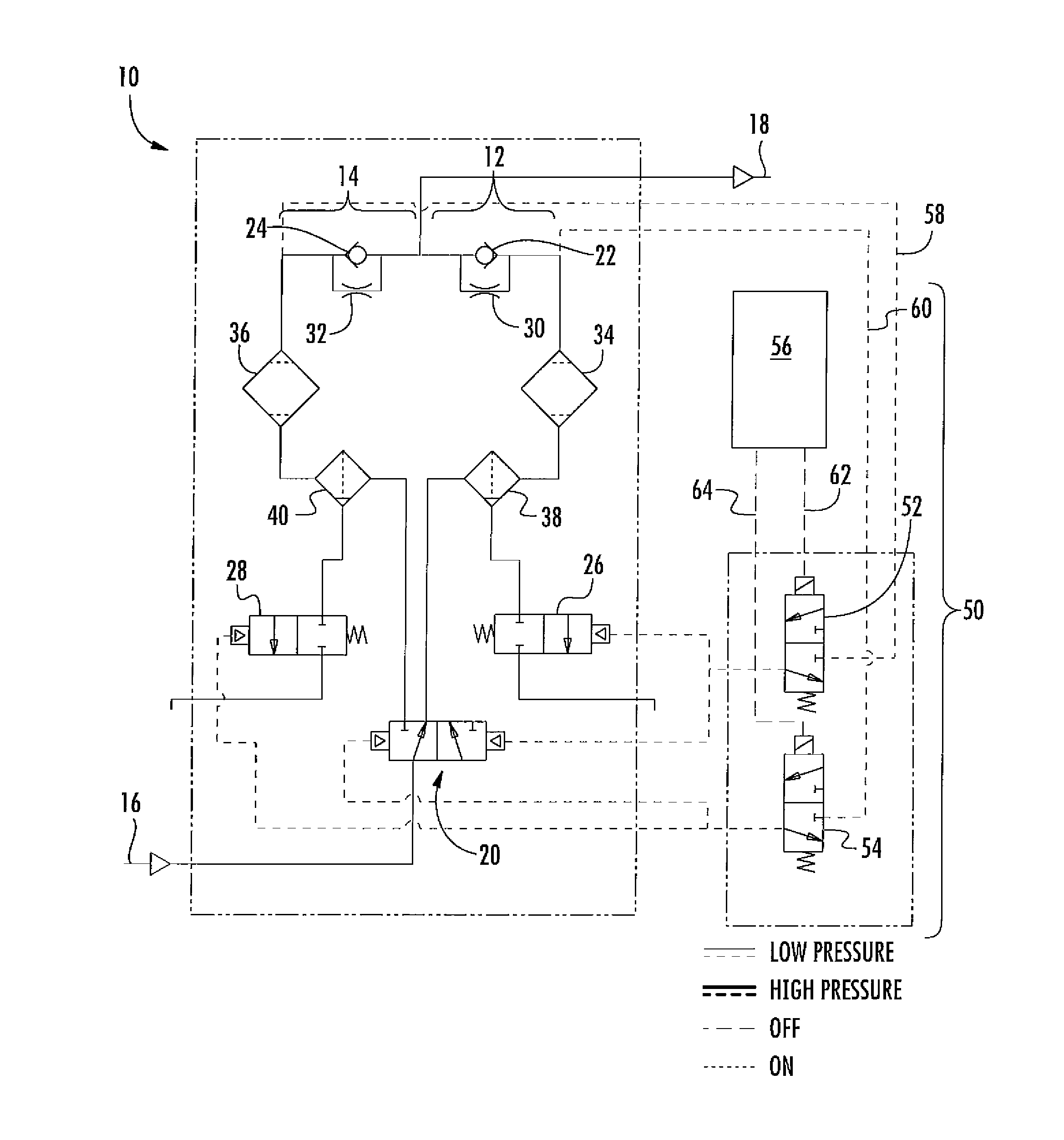
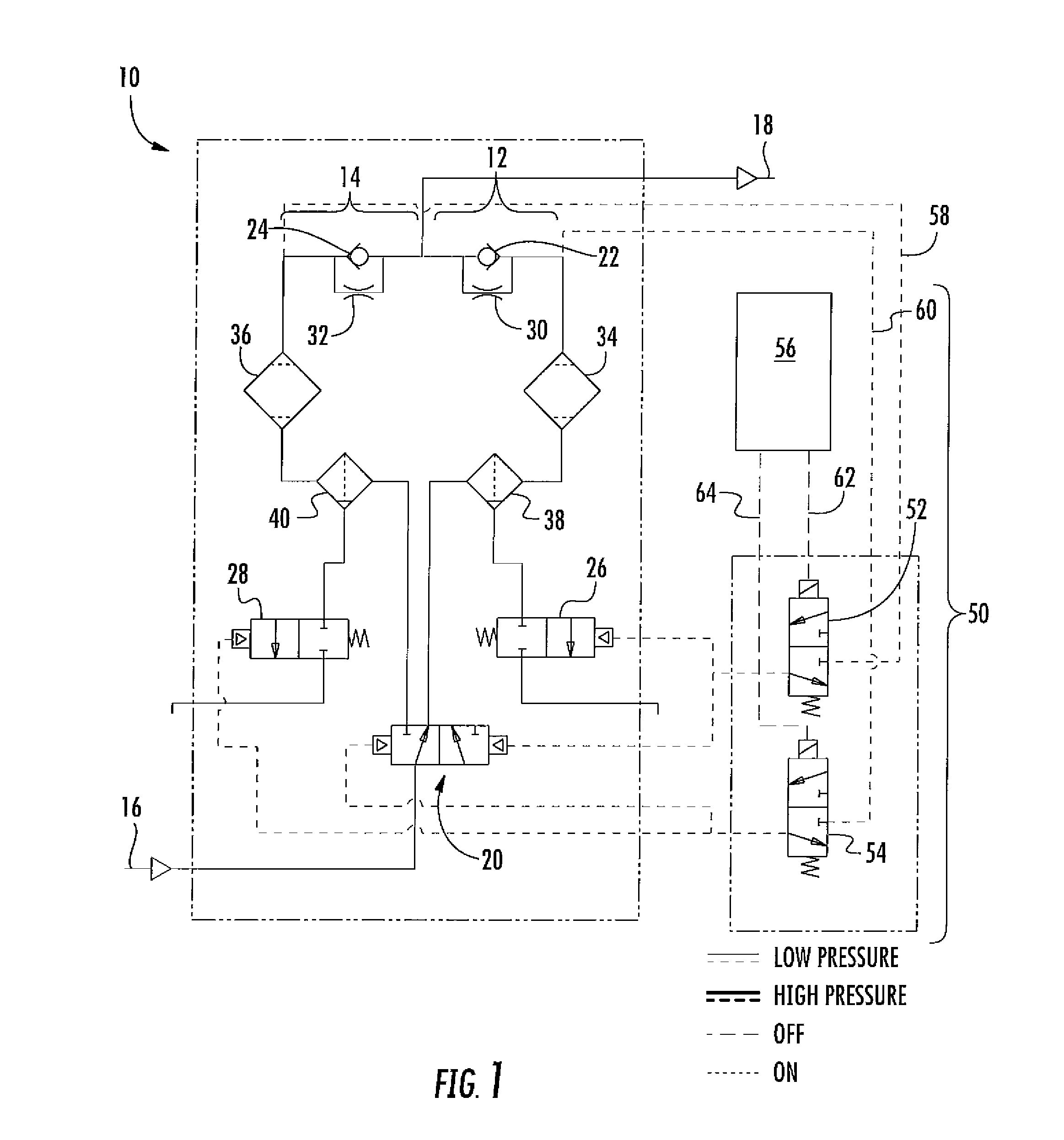
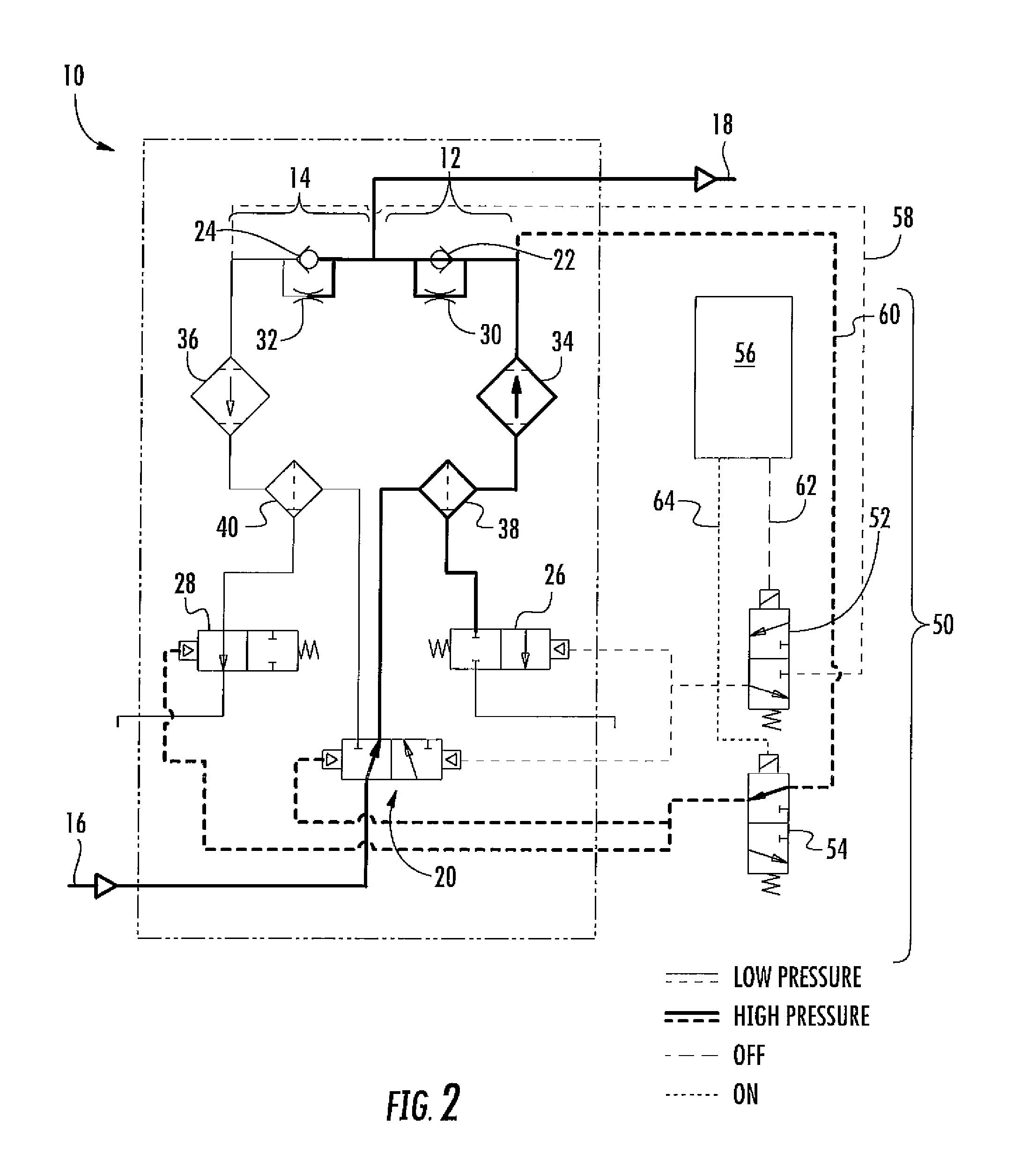
The present invention is about an air dryer that has two flow paths, each with a check valve and an exhaust valve. One flow path is opened and closed based on the position of the other valve, and a diverter valve can switch between communication with each path. An interlock prevents the diverter valve from being positioned in the wrong direction when either valve is open. The technical effect of this invention is to allow for more efficient and effective air drying in industrial applications where fluid flow needs to be controlled and directed.

Problems solved by technology

In each case, the compressed air may include moisture and other particulate contaminates which, if not removed, may accelerate fouling, corrosion, and other interference with the equipment.
However, previous air dryer designs may be susceptible to reduced effectiveness and / or complete failure in the event of improper valve alignment.

Method used


Image

  • Air dryer
  • Air dryer
  • Air dryer

Examples


Embodiment Construction

[0017]Reference will now be made in detail to present embodiments of the invention, one or more examples of which are illustrated in the accompanying drawings. The detailed description uses numerical and letter designations to refer to features in the drawings. Like or similar designations in the drawings and description have been used to refer to like or similar parts of the invention. As used herein, the terms “first,”“second,” and “third” may be used interchangeably to distinguish one component from another and are not intended to signify location or importance of the individual components. The terms “upstream,”“downstream,”“radially,” and “axially” refer to the relative direction with respect to fluid flow in a fluid pathway. For example, “upstream” refers to the direction from which the fluid normally flows, and “downstream” refers to the direction to which the fluid normally flows. Similarly, “radially” refers to the relative direction substantially perpendicular to the fluid ...


PUM


Abstract

An air dryer includes first and second flow paths. Each flow path includes a check valve that prevents fluid flow into the flow path and an exhaust valve having an open position that permits fluid flow out of the flow path and a shut position that prevents fluid flow out of the flow path. A diverter valve has a first position that provides fluid communication to the first flow path and a second position that provides fluid communication to the second flow path. An interlock operably connected to the diverter valve and the exhaust valves prevents positioning the diverter valve to the first position when the exhaust valve in the first flow path is in the open position and prevents positioning the diverter valve to the second position when the exhaust valve in the second flow path is in the open position.

Description

FIELD OF THE INVENTION[0001]The present invention generally involves an air dryer, such as may be incorporated into a compressed air system to remove moisture and other contaminants from compressed air.BACKGROUND OF THE INVENTION[0002]Compressed air is commonly used to perform a myriad of functions. For example, compressed air may be used to displace water in submarine ballast tanks to increase the buoyancy of the submarine, to operate brakes on locomotives and trucks, or to pneumatically operate valves. In each case, the compressed air may include moisture and other particulate contaminates which, if not removed, may accelerate fouling, corrosion, and other interference with the equipment.[0003]Various air dryers are known in the art to remove moisture and particulate contaminates from the compressed air. The air dryers typically include various combinations of filters and moisture separators to clean and dry the compressed air before it reaches the equipment. For equipment that re...

Claims


Application Information

Patent Timeline
Patent Type & Authority Applications(United States)
IPC IPC(8): B01D53/26
CPCB01D53/26B01D53/261B01D53/266B01D53/0454B60T17/004B01D2259/402B01D2259/4566Y10S55/17
Inventor GINDER, WILLIAM F.
Owner GRAHAM WHITE MFG
Learn More