Discontinuous shielding tapes for data communications cable

Active Publication Date: 2014-08-28
BERK TEK
View PDF10 Cites 10 Cited by
  • Summary
  • Abstract
  • Description
  • Claims
  • Application Information

AI Technical Summary

Benefits of technology

[0014]The present arrangement overcomes the drawbacks of the prior art by providing a discontinuous shielding tape, where the conductive shielding elements, disposed on the tape substrate do not form a complete electrical connection from one end of the cable to the other. Moreover, the metal shielding elements on the tape substrate are shaped and

Problems solved by technology

For example, in a typical installation, many LAN cables may be arranged next to one another, and signals in the pairs from a first cable may cause interference or crosstalk with another pair in an adjacent LAN cable.
This is a time consuming step that increases the cost to install the shielded cable.
One typical example requires a drain wire to be helically coiled around the shield which also increases the overall cable cost.
However, in doing so, this design has generated yet another drawback, particularly with respect to the signal quality within the pairs o

Method used


Image

  • Discontinuous shielding tapes for data communications cable
  • Discontinuous shielding tapes for data communications cable
  • Discontinuous shielding tapes for data communications cable

Examples


Example

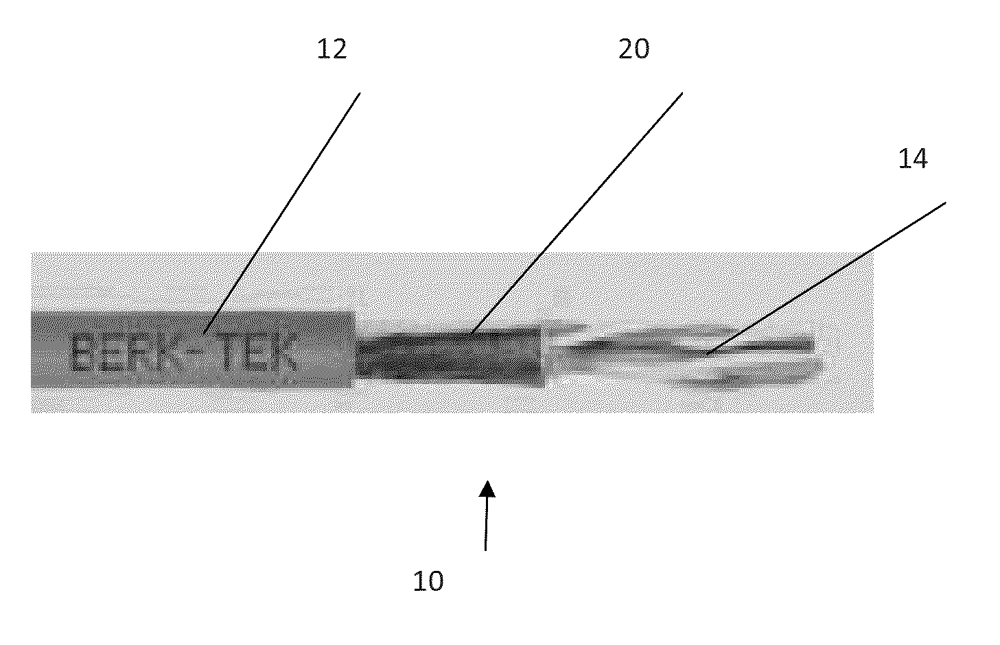
[0028]In one embodiment, FIG. 1 shows an exemplary LAN cable 10 having a jacket 12, a plurality of twisted pairs 14 and a discontinuous shield 20, disposed over pairs 14 within jacket 12. For the purpose of illustrating the salient features of the present arrangement, different versions of discontinuous shielding tape 20, shown in FIGS. 2-9, is envisioned as being applied as shown by element 20 in FIG. 1. However, it is understood that the subsequently described discontinuous shields 20, shown in FIGS. 2-9 may be equally applied to larger or smaller pair count cables, or in other communication cable designs that employ a shield.

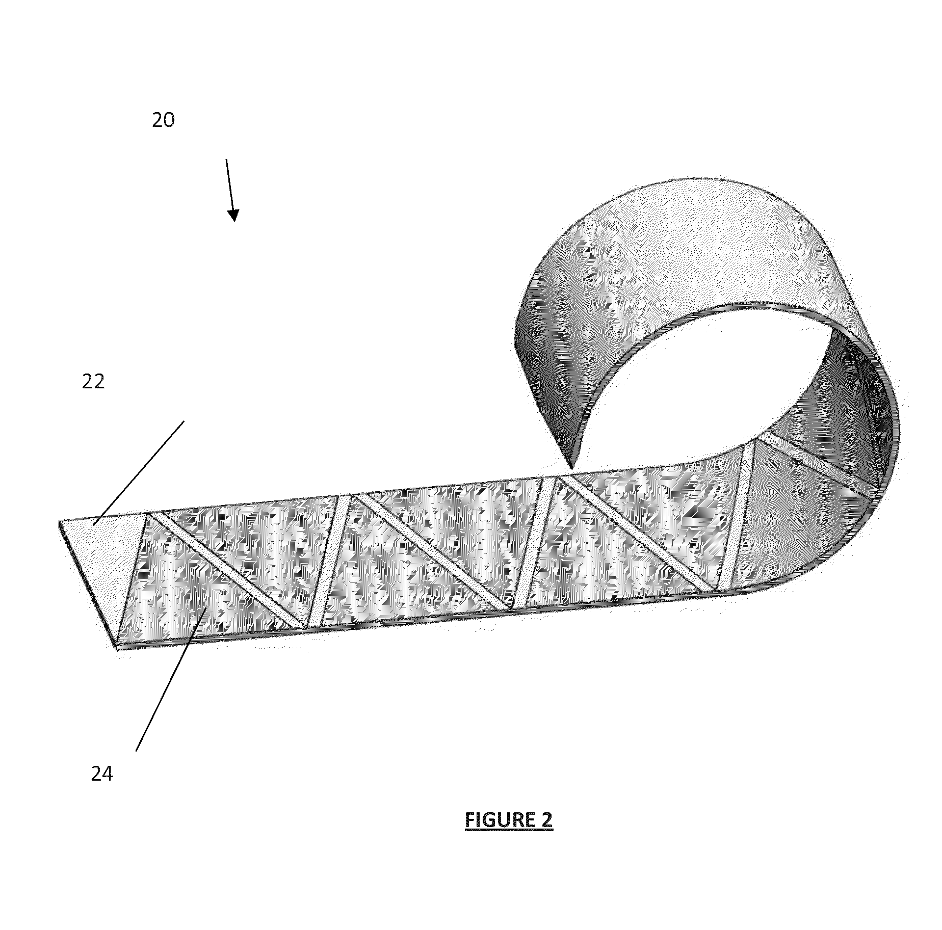
[0029]Turning to the discontinuous shielding tape 20, FIG. 2, shows a first discontinuous shielding tape 20 constructed of a first substrate 22 and a plurality of triangular shaped foil elements 24. In another arrangement, as shown in FIG. 3, triangle shaped foil elements 24 are disposed on both sides of substrate 22.

[0030]In a preferred embodiment substrate ...


PUM


Abstract

The present arrangement provides a communication cable having a plurality of twisted pair communication elements, a jacket surrounding the twisted pairs and a shield element disposed between the pairs and the jacket. The shield element is constructed as a tape substrate with a plurality of foil shielding elements disposed thereon, the foil shielding elements being formed in the shape of triangles and arranged on the substrate with at least a first foil shield element having a base of its triangle shape disposed substantially parallel to a longitudinal edge of the tape substrate. Each subsequent triangle is disposed on the tape substrate at a distance apart from the first triangle foil shielding element with a base of its triangle shape disposed substantially parallel to an opposite longitudinal edge of the tape substrate.

Description

BACKGROUND[0001]1. Field of the Invention[0002]This application relates to a shielding tape. More particularly, this application relates to a shielding tape for LAN (Local Area Network) cables.[0003]2. Description of the Related Art[0004]LAN or network type communication cables are typically constructed of a plurality of twisted pairs (two twisted conductors), enclosed within a jacket. A typical construction is to have four twisted pairs inside of a jacket, but many other larger pair count cables are available.[0005]Care is taken to construct these cables in a manner to prevent cross talk with adjacent cables. For example, in a typical installation, many LAN cables may be arranged next to one another, and signals in the pairs from a first cable may cause interference or crosstalk with another pair in an adjacent LAN cable. In order to prevent this, the lay length or twist rate of the pairs in a cable are varied differently from one another. Additionally, when pairs in adjacent cable...

Claims


Application Information

Patent Timeline
IPC IPC(8): H01B11/04
CPCH01B11/1008H01B11/04H01B11/06
Inventor KROUSHL, PAULJIANG, QIBOHEFFNER, GREGKELLER, JOSHUA
Owner BERK TEK
Why Eureka
Try Eureka