Cartridge, liquid ejection device, and liquid ejection system

a technology of liquid ejection device and cartridge, which is applied in the direction of printing, etc., can solve the problems of unstable contact state between the contact member and the terminal, inability to maintain the electrical connection between the cartridge and the printer in a favorable state, and difficulty in suppressing the positional shift of the terminal provided on the cartridge, so as to raise the reliability of contact

Active Publication Date: 2014-08-28
SEIKO EPSON CORP
View PDF1 Cites 5 Cited by
  • Summary
  • Abstract
  • Description
  • Claims
  • Application Information

AI Technical Summary

Benefits of technology

[0027]According to the cartridge of this mode, when mounting the cartridge, the first end portion collides with the first opposing portion even if the cartridge has excessively deviated from the designed position in the liquid ejection device. Accordingly, it is possible for the distance for which the conductive contact member rubs against the terminal to fall in an appropriate range, thus enabling raising the reliability of contact between the conductive contact member and the terminal. For example, it is possible to prevent the rubbing region of the conductive contact member from moving beyond the terminal and arriving at a portion where the terminal is not arranged.
[0028](9) Another mode of the invention provides a cartridge configured to be removably mounted to a liquid ejection device including a first engag

Problems solved by technology

When the cartridge is subjected to various external forces, the state of contact between the contact members and the terminals becomes unstable, and there are cases where the electrical connection between the cartridge and the printer cannot be maintained in a favorable state.
However, with the

Method used


Image

  • Cartridge, liquid ejection device, and liquid ejection system
  • Cartridge, liquid ejection device, and liquid ejection system
  • Cartridge, liquid ejection device, and liquid ejection system

Examples


first embodiment

A. First Embodiment

[0144]A-1: Configuration of Liquid Ejection System 1

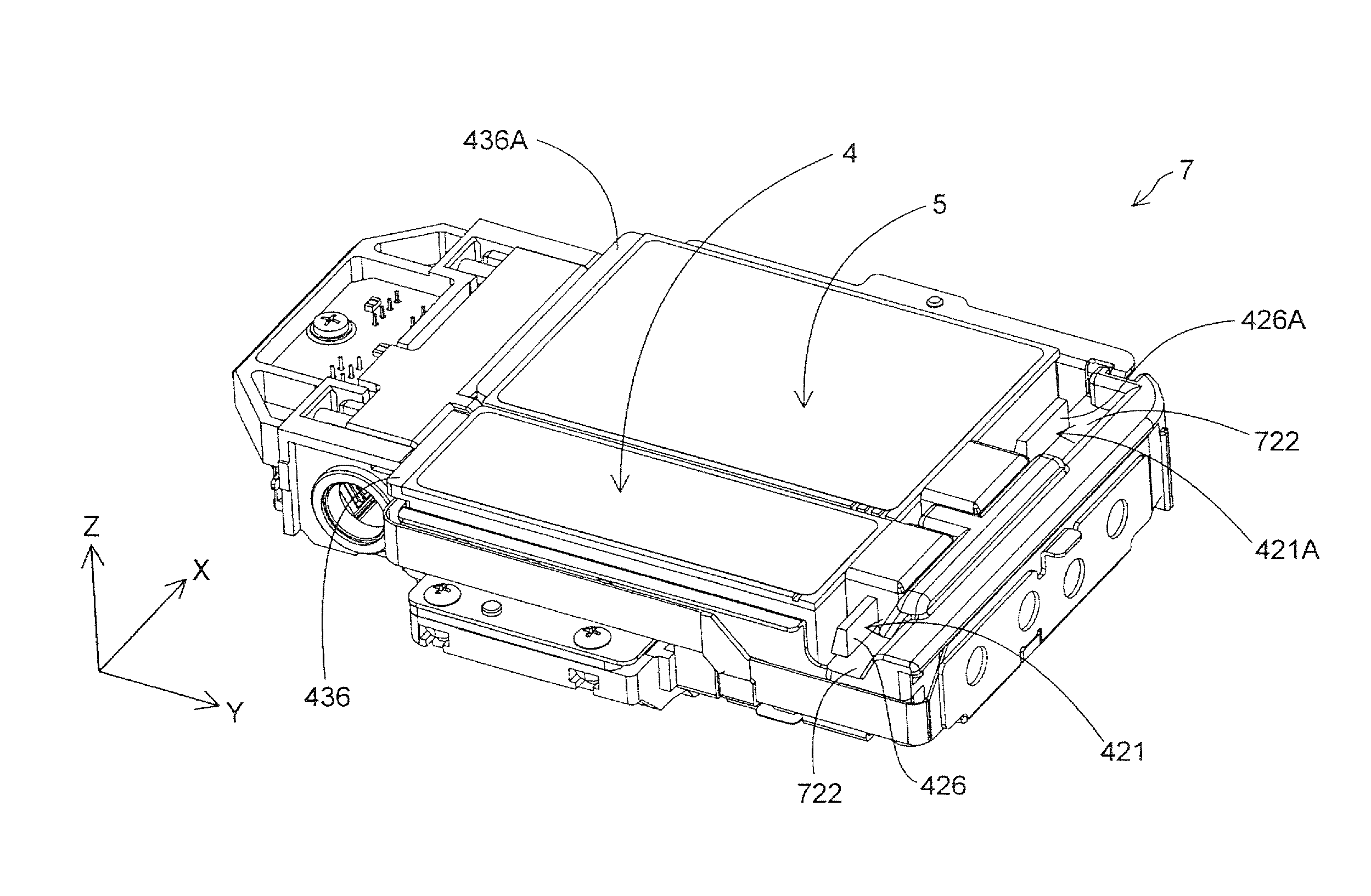
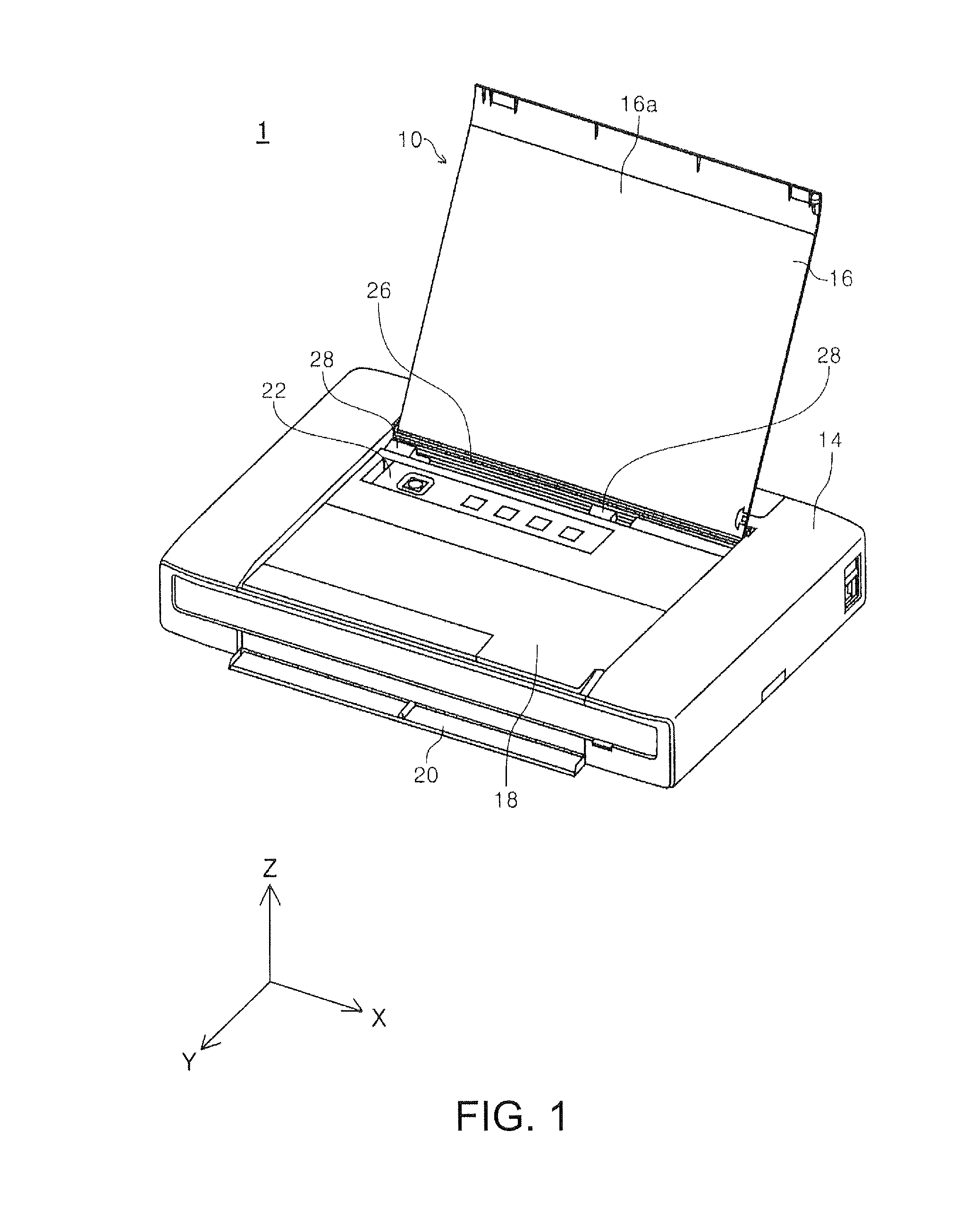
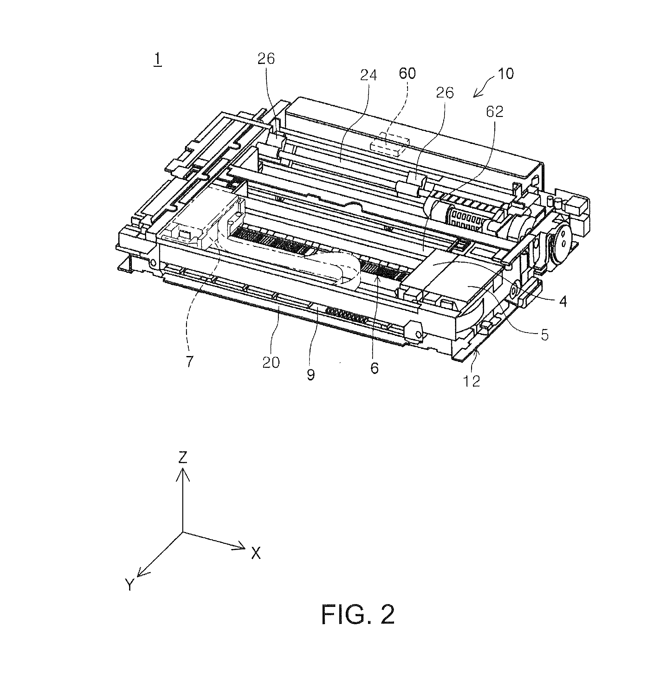
[0145]FIG. 1 is a perspective view of the schematic configuration of a liquid ejection system 1. FIG. 2 is a perspective view of the internal configuration of the liquid ejection system 1. Mutually orthogonal X, Y, and Z axes are shown in FIGS. 1 and 2. These X, Y, and Z axes are used when necessary in later-described figures as well. The X, Y, and Z axes in FIGS. 1 and 2 correspond to the X, Y, and Z axes in the other figures as well. The liquid ejection system 1 includes a printer 10 serving as a liquid ejection device, and two types of cartridges 4 and 5. As shown in FIG. 2, in the liquid ejection system 1 of this embodiment, the cartridges 4 and 5 are removably mounted to a cartridge mounting portion 7 of the printer 10. The cartridge mounting portion 7 is provided on a carriage that includes a head for discharging ink. Hereinafter, the cartridge 4 will also be referred to as the “first cartridge 4”, and the ...

second embodiment

B: Second Embodiment

[0316]FIG. 38 is a diagram for describing a cartridge mounting portion 7a of a second embodiment. A difference between the cartridge mounting portion 7a and the cartridge mounting portion 7 (FIG. 4A) of the first embodiment is that the cartridge mounting portion 7a includes partition walls 743 and 745. Since the other configurations are similar to those of the cartridge mounting portion 7, the same reference signs will be used for the similar configurations, and descriptions will not be given for them. Besides the cartridge mounting portion 7a, the configuration of the printer 10 is also similar to the configuration in the first embodiment.

[0317]The partition walls 743 and 745 extend in the vertically upward direction from the device-side bottom wall 74. They are located between the liquid introduction portion 703c and the liquid introduction portion 703d. The partition wall 745 is located between the liquid introduction portion 703b and the liquid introduction p...

third embodiment

C: Third Embodiment

[0322]C-1: Configuration and Effects of Second Cartridge 5b

[0323]FIG. 41 is a diagram for describing a second cartridge 5b of a third embodiment. FIG. 42 is a cutaway view of the second cartridge 5b of the third embodiment. FIG. 43 is a cross-sectional view of the second cartridge 5b. A difference between the second cartridge 5b and the second cartridge 5a (FIG. 40) of the second embodiment is that the second cartridge 5b has an interior release flow channel 910 (FIG. 43). Since the other configurations are similar to those of the second cartridge 5a (FIG. 40), the same reference signs will be used for the similar configurations, and descriptions will not be given for them. Also, the configuration of the printer to which the second cartridge 5b is mounted is similar to the configuration of the printer of the second embodiment.

[0324]As shown in FIGS. 41 and 42, two grooves 481A and 481B that extend from the liquid supply portion 480A1 to the third plane 43A are fo...


PUM


Abstract

The invention provides a technique for raising the reliability of contact between contact members of a liquid ejection device and terminals of a cartridge. A cartridge is configured to be removably mounted to a liquid ejection device including a first engaging portion and a conductive contact member that has elastic force and that is arranged so as to be adjacent to the first engaging portion. The cartridge includes a terminal arranged so as to be able to come into contact with the conductive contact member, and a first hook that can be engaged with the first engaging portion.

Description

BACKGROUND[0001]1. Technical Field[0002]The entire disclosure of Japanese Patent Application No.: 2013-039456, filed Feb. 28, 2013 is expressly incorporated by reference herein.[0003]The present invention relates to a technique that is related to cartridges for storing a liquid.[0004]2. Related Art[0005]There is a conventionally known technique of employing an ink cartridge for storing ink (also simply called a “cartridge”) as a technique for supplying ink to a printer, which is one example of a liquid ejection device. This cartridge includes a liquid storage portion for storing ink serving as the liquid, and a liquid supply portion for supplying the ink in the liquid storage portion to a printer.[0006]There is also known to be a cartridge that includes a circuit substrate for exchanging information with a printer (e.g., see JP-A-2008-074100). This circuit substrate stores information regarding the cartridge, such as information indicating the manufacturing date of the cartridge and...

Claims


Application Information

Patent Timeline
IPC IPC(8): B41J2/175
CPCB41J2/1752B41J2/17526B41J2/1753
Inventor OYA, SHUN
Owner SEIKO EPSON CORP
Why Eureka
Try Eureka