Apparatus and Method for Oil Equalization in Multiple-Compressor Systems

a technology of multiple compressors and apparatuses, applied in the direction of machines/engines, liquid fuel engines, rotary/oscillating piston pump components, etc., can solve the problem of premature presentation of oil, and achieve the effect of facilitating relative movemen

Active Publication Date: 2014-08-28
BITZER KUEHLMASCHINENBAU GMBH
View PDF5 Cites 37 Cited by
  • Summary
  • Abstract
  • Description
  • Claims
  • Application Information

AI Technical Summary

Benefits of technology

[0006]In a particular aspect, embodiments of the invention provide a scroll compressor that includes a housing having an inlet port and an outlet port. The housing has a sidewall with an internal surface surrounding an internal chamber with an oil sump at a bottom of the internal chamber. Scroll compressor bodies are located in the housing. The scroll compressor bodies have respective bases and respective scroll ribs that project from the respective bases, and which mutually engage. The scroll compressor bodies are operative to compress fluid entering from the inlet port and discharge compressed fluid toward the outlet port. A motor provides a rotational output operatively driving one of the scroll compressor bodies to facilitate relative movement for the compression of fluid. The scroll compressor further includes an oil equalization fitting mounted through the sidewall arranged below the inlet port to communicate oil to and from the oil sump. The oil equalization fitting includes an extension projecting inwardly from the internal surface and into the internal chamber.

Problems solved by technology

When oil is circulated and returned to the oil-supplying compressor, the oil may run down an interior surface of the oil-supplying compressor housing such that the oil is presented prematurely at the opening of the oil-supplying compressor.

Method used


Image

  • Apparatus and Method for Oil Equalization in Multiple-Compressor Systems
  • Apparatus and Method for Oil Equalization in Multiple-Compressor Systems
  • Apparatus and Method for Oil Equalization in Multiple-Compressor Systems

Examples


Embodiment Construction

[0033]The following detailed description describes embodiments of the invention as applied in a multi-compressor refrigeration system. However, one of ordinary skill in the art will recognize that the invention is not necessarily limited to refrigeration systems. Embodiments of the invention may also find use in other systems where multiple compressors are used to supply a flow of compressed gas.

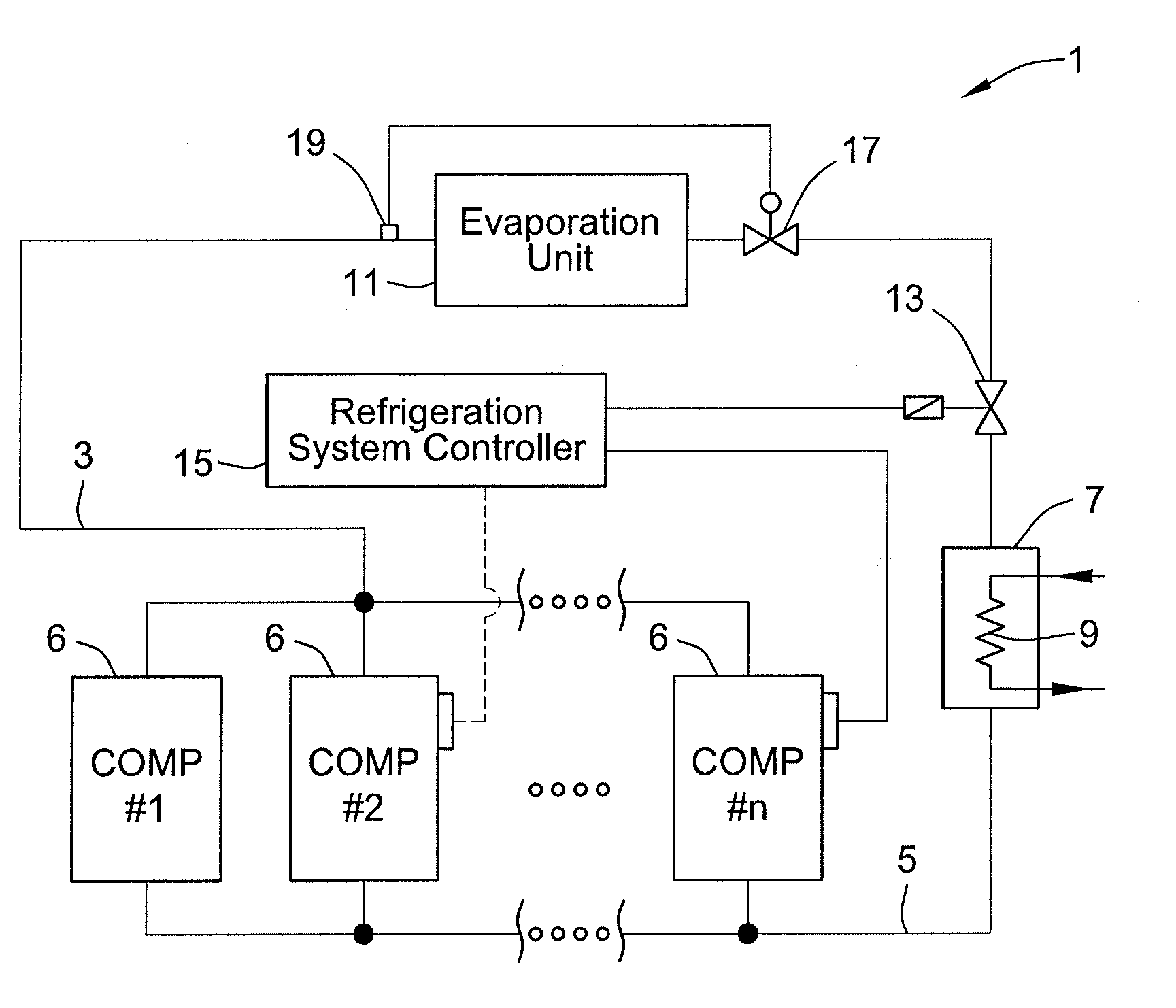
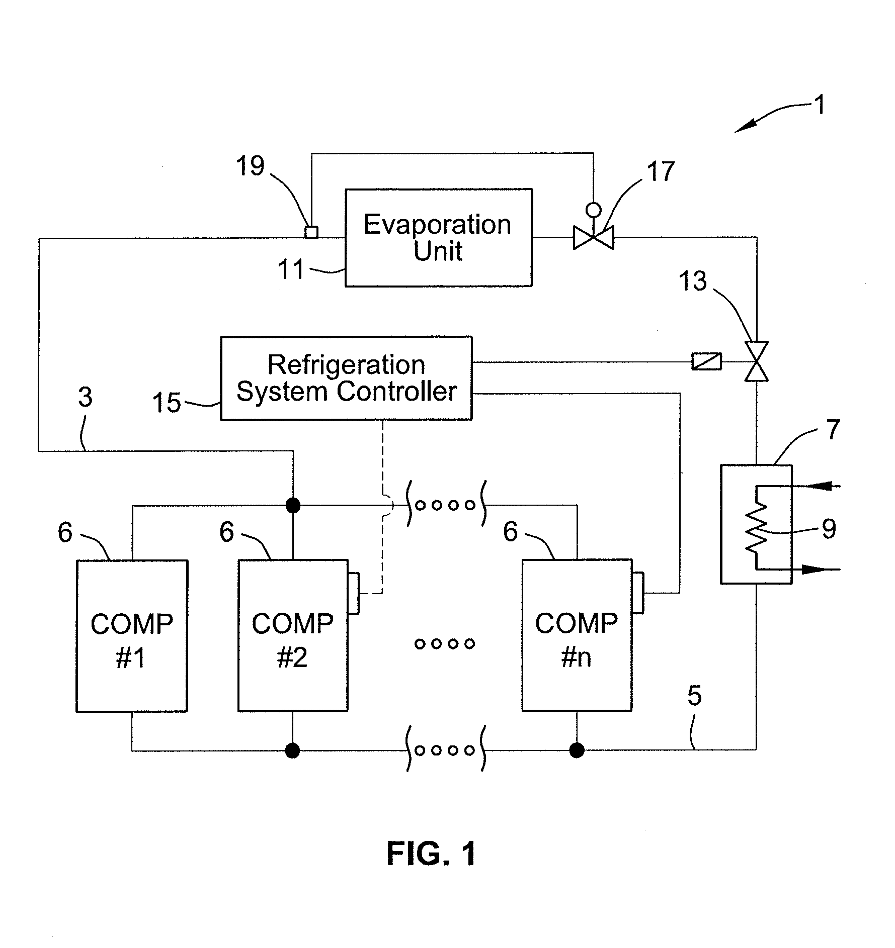
[0034]FIG. 1 provides a schematic illustration of an exemplary multiple-compressor refrigeration system 1 having N compressors 6. The N compressors 6 of refrigeration system 1 are connected in a parallel circuit having inlet flow line 3 that supplies a flow of refrigerant to the N compressors 6, and outlet flow line 5 that carries compressed refrigerant away from the N compressors 6. In certain embodiments, the flow of refrigerant carries oil entrained within the flow, the oil used to lubricate moving parts of the compressor 6. As shown, the outlet flow line 5 supplies a condenser 7. In a pa...


PUM


Abstract

A method of operating a refrigeration system, that includes providing a plurality of compressors connected in parallel. The plurality of compressors includes a plurality of scroll compressors. The method further includes returning circulated refrigerant to the plurality of compressors, the circulated refrigerant having oil entrained therein. Returning circulated refrigerant to the plurality of compressors includes returning more oil to one of the plurality of compressors than to another of the plurality of compressors. The method also includes supplying oil from one of the plurality of compressors to at least one other of the plurality of compressors. Supplying oil from one of the plurality of compressors includes supplying oil from the one of the plurality of compressors having an opening in its housing. A fitting is assembled into the opening. The fitting protrudes through the housing into an interior portion of the housing.

Description

CROSS-REFERENCE TO RELATED PATENT APPLICATIONS[0001]This patent application claims the benefit of U.S. Provisional Patent Application No. 61 / 770,868, filed Feb. 28, 2013, the entire teachings and disclosure of which are incorporated herein by reference thereto.FIELD OF THE INVENTION[0002]This invention generally relates to multi-compressor refrigeration systems.BACKGROUND OF THE INVENTION[0003]A particular example of the state of the art with respect to suction gas distribution in a parallel compressor assembly is represented by WIPO patent publication WO2008 / 081093 (Device For Suction Gas Distribution In A Parallel Compressor Assembly, And Parallel Compressor Assembly), which shows a distribution device for suction gas in systems with two or more compressors, the teachings and disclosure of which is incorporated in its entirety herein by reference thereto. A particular example of oil management in systems having multiple compressors is disclosed in U.S. Pat. No. 4,729,228 (Suction ...

Claims


Application Information

Patent Timeline
Patent Type & Authority Applications(United States)
IPC IPC(8): F04C29/02F04C11/00
CPCF04C29/021F04C11/003F04C23/001F04C23/008F04C2240/806F04C2240/809
Inventor FRASER, BRUCE A.
Owner BITZER KUEHLMASCHINENBAU GMBH
Why Eureka
Try Eureka