Method of thermally drawing structured sheets
a technology of structured sheets and thermal gradients, applied in the field of methods for drawing materials from preforms, can solve the problems of limiting the shapes that can be drawn and the method of applying thermal gradients
- Summary
- Abstract
- Description
- Claims
- Application Information
AI Technical Summary
Problems solved by technology
Method used
Image

Examples
example 1
[0076]Let's assume that one wants to draw a polymer or glass layer from 1 mm thickness to 100 nm. This film can be embedded into a slab-like preform. But it is not practical to drawn a preform down by 1000 times in one draw. So, we can draw this preform once by a factor or F1, embed the drawn film in a second slab-like preform, and draw it down by another factor F2 in a way that F1*F2=1000.
example 2
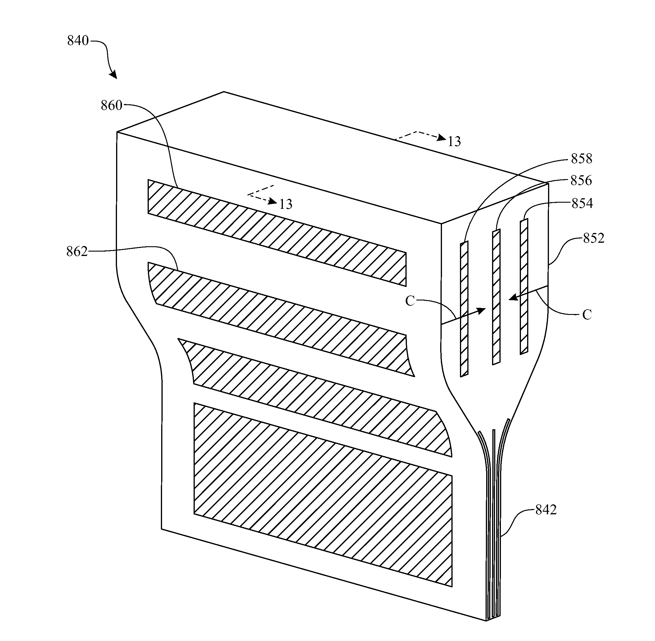
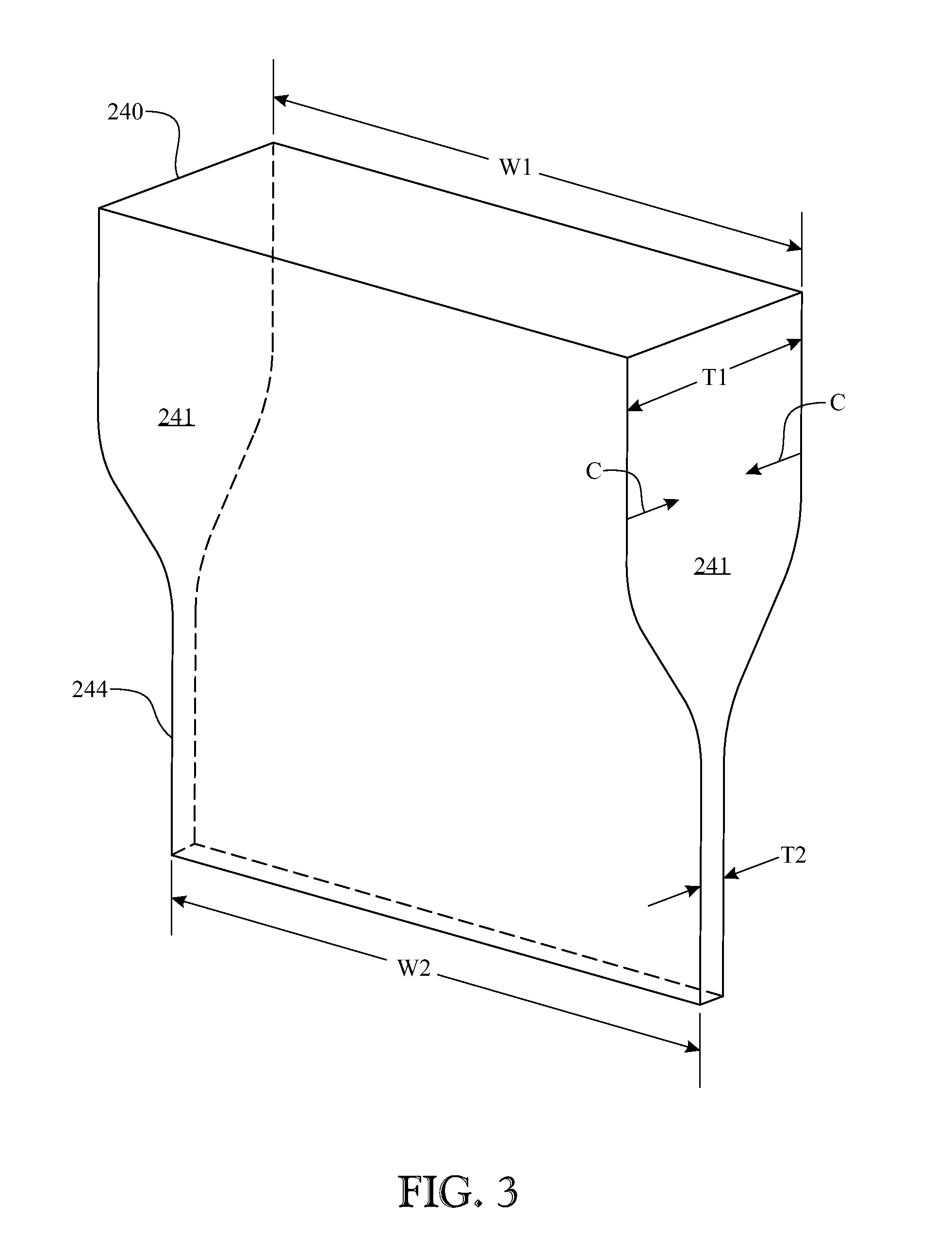
[0077]Let's assume one wants to have a periodic structure in a final film whose direction of periodicity (grating vector, in optics terms) is along the transverse direction (width) W1 of the final film. We want the periodic structure to have alternate layer thicknesses of 1 micrometer and 2 micrometers, and we want the final film to have a total thickness of 0.1 mm. We can assemble a first slab-like preform that includes a multi-layer stack of the two materials with initial thicknesses 100 micro-meters and 200 micro-meters, respectively. We can then draw this preform by 100 times so that bilayers have the target thicknesses of 1 micron and 2 microns. The direction of periodicity, however, is still across the thickness of the first preform / film (T1 or T2). Then we can cut the film along the longitudinal direction in pieces 10 mm wide, rotate (flip) them by 90 degrees and stack them in the direction of preform width (W). We can assemble (or embed) them into a second preform which is n...
example 3
[0078]One can take the following steps to create a layered film with changing layer thickness. Layers of different thicknesses can be stacked in the initial preform before the preform is consolidated and drawn. However, this may not be very practical or efficient when complex layer structures are desired or when layers in the preform level are supposed to be very thin and therefore difficult to handle. For example, discrete rugate structures where each periodic cycle of refractive index variation is formed of several sub-layers each in the range of five to fifty nanometers. Such sub-layers should be sub-micrometer thick in the preform level. A person of ordinary skill would recognize that handling delicate sub-micrometer films (if available in free standing form) is very difficult. In such cases, one can instead obtain the final film through two or more steps of stacking and re-drawing. As another example, if a chirped layered structure is needed with final layer thicknesses ranging...
PUM
| Property | Measurement | Unit |
|---|---|---|
| Temperature | aaaaa | aaaaa |
| Transmission | aaaaa | aaaaa |
| Mechanical properties | aaaaa | aaaaa |
Abstract
Description
Claims
Application Information
 - R&D Engineer
- R&D Manager
- IP Professional
- Industry Leading Data Capabilities
- Powerful AI technology
- Patent DNA Extraction
Browse by: Latest US Patents, China's latest patents, Technical Efficacy Thesaurus, Application Domain, Technology Topic.
© 2024 PatSnap. All rights reserved.Legal|Privacy policy|Modern Slavery Act Transparency Statement|Sitemap