Position Detecting System

a detection system and position technology, applied in the direction of electrical/magnetically converting the output of the sensor, instruments, measurement devices, etc., can solve the problems of increasing the power loss reducing the accuracy of the sensing technique, and loosing the power of the time-varying magnetic field

Active Publication Date: 2014-09-04
TEXAS INSTR INC
View PDF4 Cites 58 Cited by
  • Summary
  • Abstract
  • Description
  • Claims
  • Application Information

AI Technical Summary

Benefits of technology

[0189]A further advantage of the position detecting systems is that when multiple sensors are used, the multiple sensors enable position sensing in multidimensional space, where each sensor adds one dimension. This, in turn, enables the elimination of position tolerances in one or more spatial dimensions, where each additional sensor enables the elimination of one dimension. The use of multiple sensors also enables the elimination of temperature drift. Temperature drift can be eliminated by creating a differential setup and a ratiometric setup, and by using a reference sensor and a reference target. Temperature drift can also be eliminated by using multiple sensors with different shaped targets.

Problems solved by technology

When the target is exposed to the time varying magnetic field, the time varying magnetic field induces eddy currents in the surface of the target, which causes the time varying magnetic field to lose power.
The increase in the magnitudes of the eddy currents causes the time varying magnetic field to lose more power.
One of the disadvantages of the proximity switch is that the accuracy of this sensing technique decreases rapidly with the longitudinal distance to the coil, with the usable sensing range being limited to approximately 50% of the coil diameter.
However, the magnetic flux density changes in a highly non-linear fashion along the longitudinal axis.

Method used


Image

  • Position Detecting System
  • Position Detecting System
  • Position Detecting System

Examples


Embodiment Construction

[0038]This description and the figures disclose example embodiments and applications that illustrate various aspects and technical features of the invention disclosed and claimed in this specification. Known circuits, functions and operations are not described in detail to avoid unnecessarily obscuring the principles and features of the claimed invention.

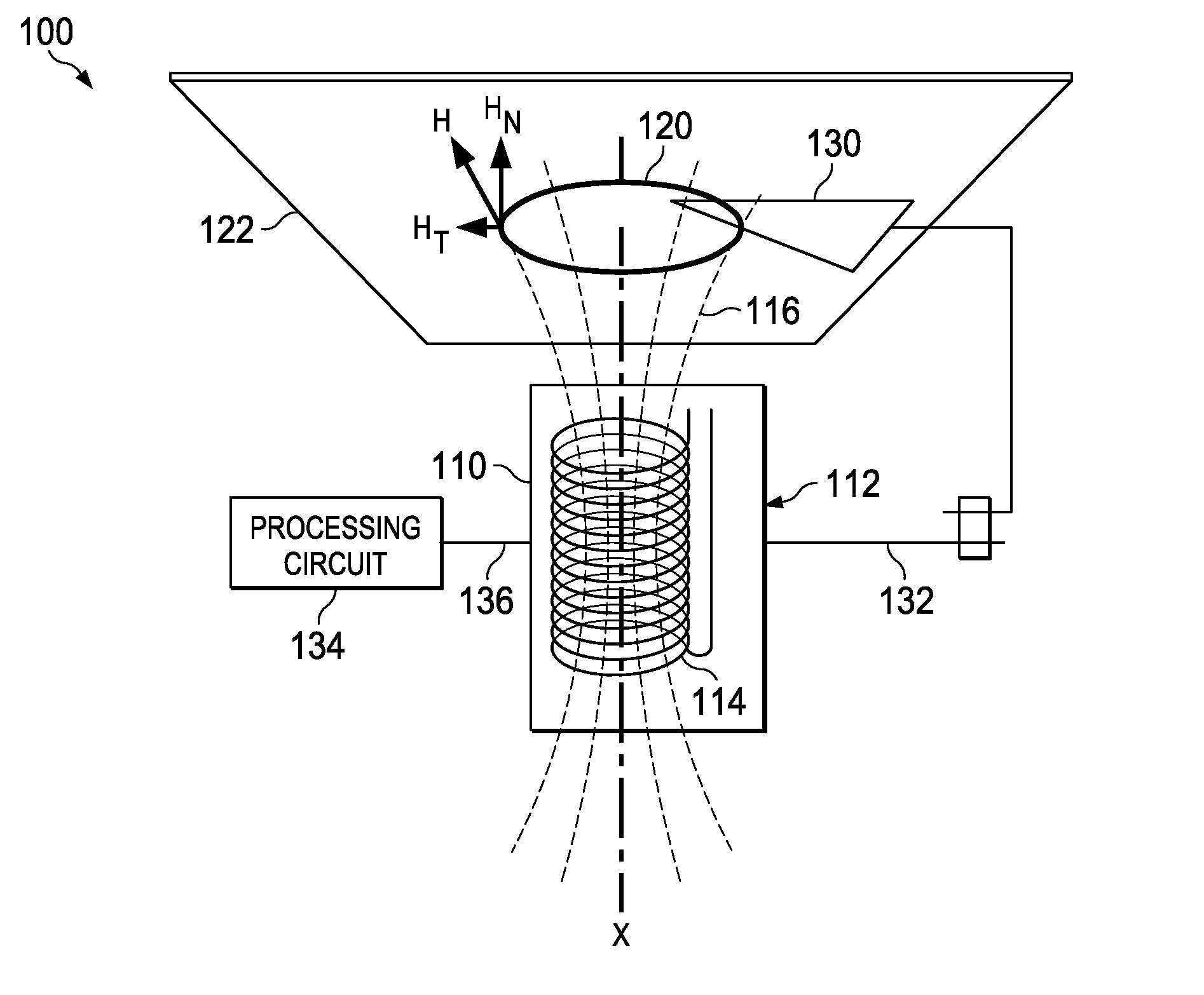
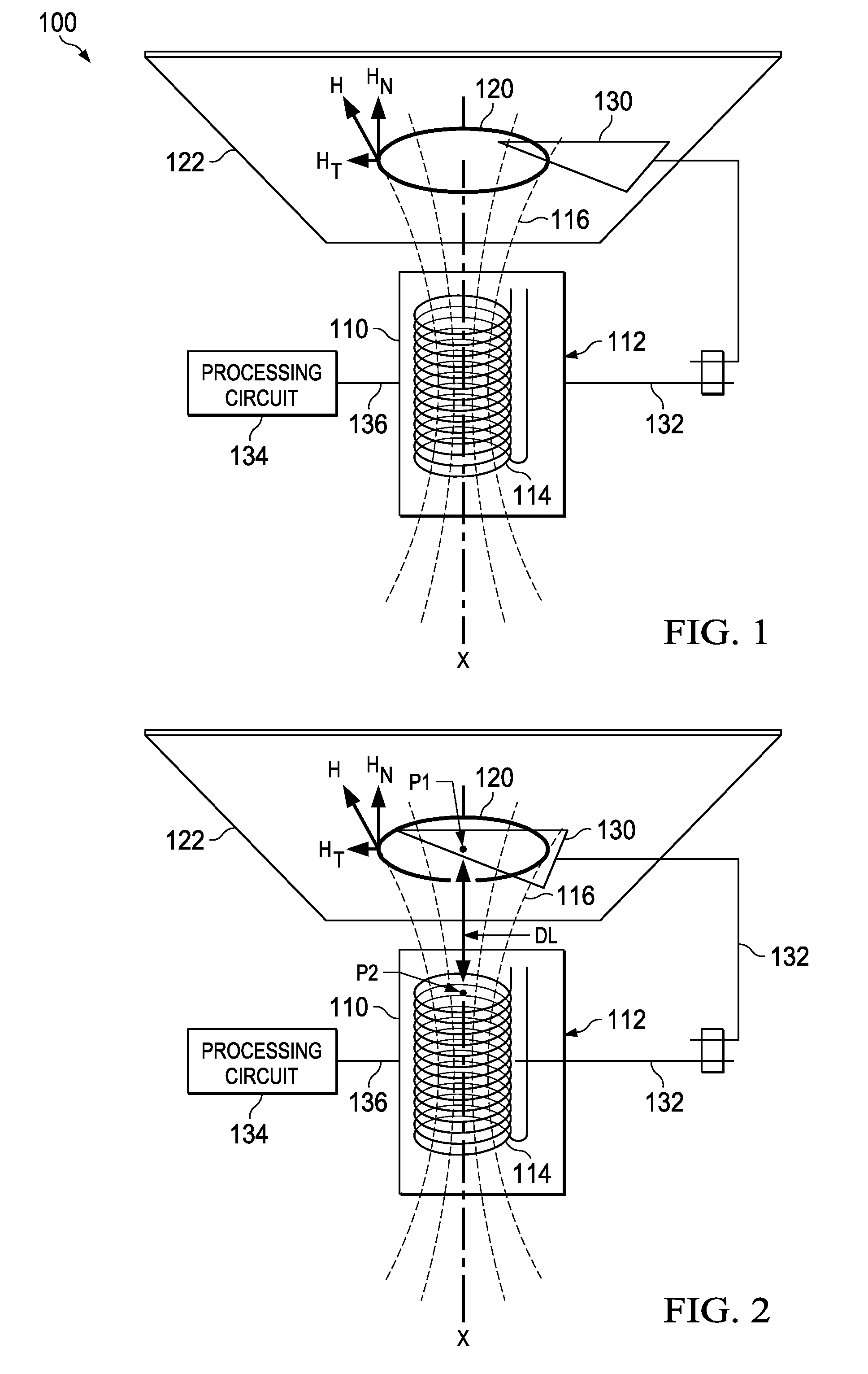
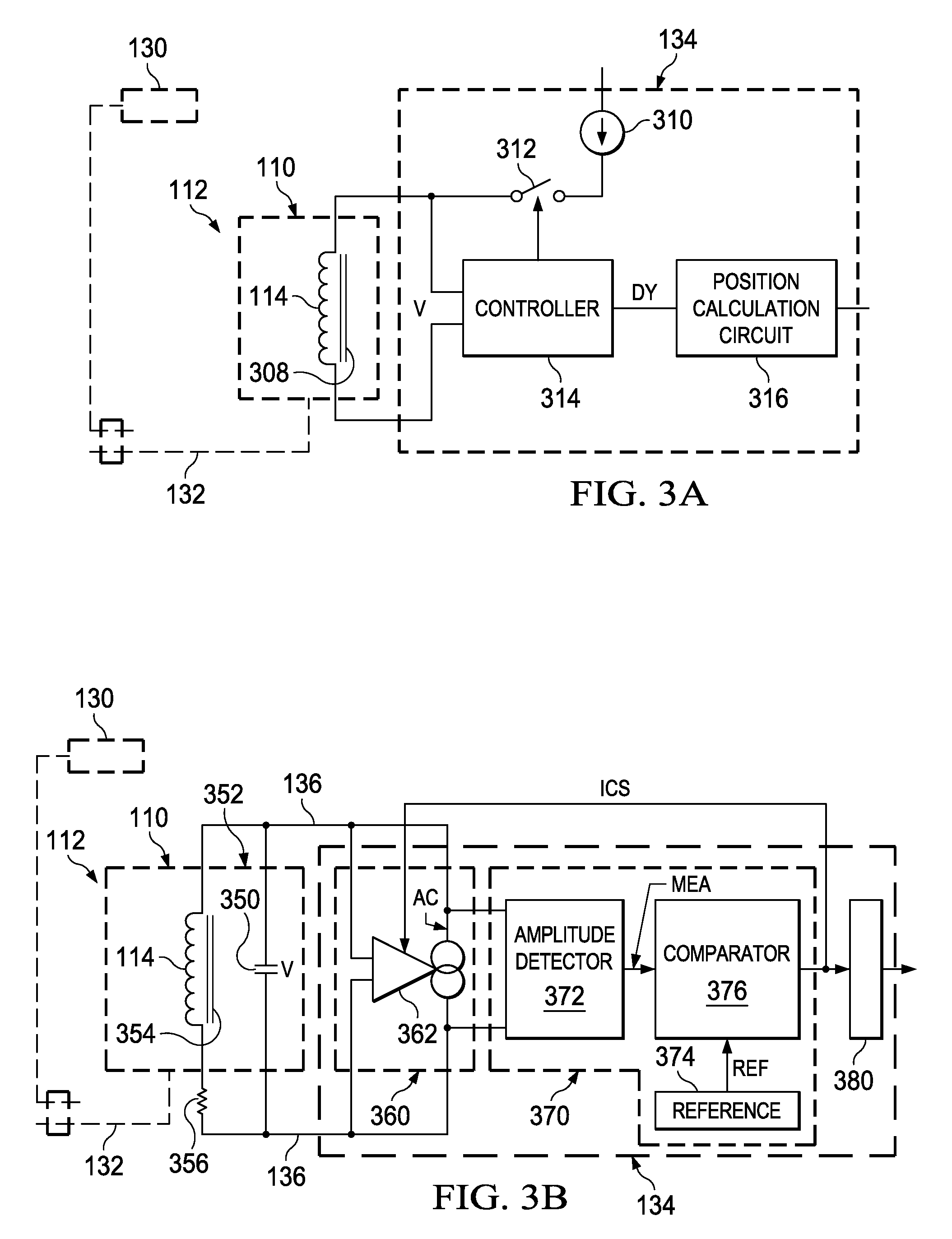
[0039]A position detecting system of the present invention includes one or more coils, electronics that are connected to the coils, and one or more electrically conductive targets that are partially exposed to the magnetic fluxes of the one or more coils. The electronics sense the characteristics of the coils, such as the coil quality or Q factor at the excitation frequency or the inductances of the coils. Both are a function of the total amount of magnetic flux that a target receives from a coil.

[0040]The position of the one or more targets is determined within a plane that lies perpendicular to the longitudinal axes of the one or ...


PUM


Abstract

A position detecting system detects and responds to the movement of a target through a sensing domain area of a plane. The movement causes the amount of the target that lies within a sensing domain area to change. A portion of the target always lies within at least one of the sensing domain areas of the plane.

Description

[0001]This application claims benefit from Provisional Application No. 61 / 772,290 filed on Mar. 4, 2013 for George Pieter Reitsma, Provisional Application No. 61 / 772,324 filed on Mar. 4, 2013 for George Pieter Reitsma et al., Provisional Application No. 61 / 838,084 filed on Jun. 21, 2013 for George Pieter Reitsma et al., and Provisional Application No. 61 / 877,759 filed on Sep. 13, 2013 for Jonathan V. Baldwin et al.BACKGROUND OF THE INVENTION[0002]1. Field of the Invention[0003]The present invention relates to detecting systems and, more particularly, to a position detecting system.[0004]2. Description of the Related Art[0005]An eddy current sensor is a position detecting system that commonly includes an inductor, a target, and a processing circuit. The inductor, which is typically implemented with a coil, senses changes in a time varying magnetic field that result from the movement of the target within the time varying magnetic field, while the processing circuit responds to changes...

Claims


Application Information

Patent Timeline
Patent Type & Authority Applications(United States)
IPC IPC(8): G01D5/20
CPCG01D5/2006G01D5/202H03H2/005
Inventor REITSMA, GEORGE PIETERHENDERSON, RICHARD DEANBALDWIN, JONATHAN
Owner TEXAS INSTR INC
Why Eureka
Try Eureka