Eureka AIR delivers breakthrough ideas for toughest innovation challenges, trusted by R&D personnel around the world.

Prosthetics using curved dampening cylinders

a dampening cylinder and cylinder technology, applied in the field of prosthetics, can solve the problems of changing the “effective heel height”, the slope of the terrain, and the steep inclines, and achieve the effect of reducing the component count and wear

Active Publication Date: 2014-09-04
COLLEGE PARK IND INC
View PDF3 Cites 17 Cited by
  • Summary
  • Abstract
  • Description
  • Claims
  • Application Information

AI Technical Summary

Benefits of technology

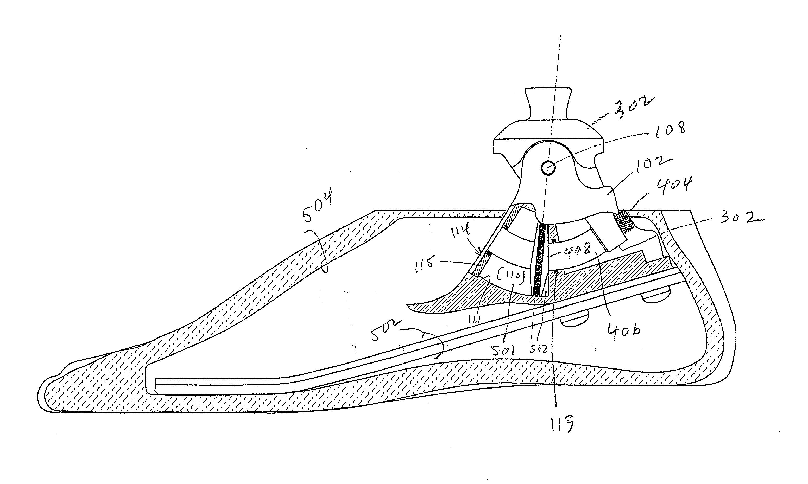
The invention is about prosthetic joints and limbs that use a single, curved cylinder to reduce the number of components and wear and tear. For example, a prosthetic foot / ankle only requires a housing, an ankle component, and a piston that moves within the housing during walking. The technical effect is that this reduces the complexity and reliability of prosthetic joints and limbs.

Problems solved by technology

These issues include changes in “effective heel height” and changes in the slope of the terrain encountered.
Artificial limbs may function properly over smooth, horizontal surfaces or on slight inclines, but steeper inclines present problems, particularly when walking downhill.
If the angle of the foot is not adequately adjustable, only the heel may make ground contact, making it difficult to accommodate the user's body weight and avoid buckling of the knee.
Manual, mechanical adjustments are often difficult to set or calibrate, and do not automatic adjust for changes in heel height or varying terrain slope.
One problem with this design is that the hydraulic cylinder is oriented along the foot, resulting in a bulky structure.
Although the solution described in the '265 patent achieves a more compact package, it suffers from the same drawback as other prostheses that utilize a conventional hydraulic cylinder; namely, since the ankle rotates and the cylinder is straight, some form of linkage must be includes to convert pivoting motion to reciprocal.
These linkages need pivot axes of their own, resulting in more moving parts and places where wear can occur.

Method used


Image

  • Prosthetics using curved dampening cylinders
  • Prosthetics using curved dampening cylinders
  • Prosthetics using curved dampening cylinders

Examples


Embodiment Construction

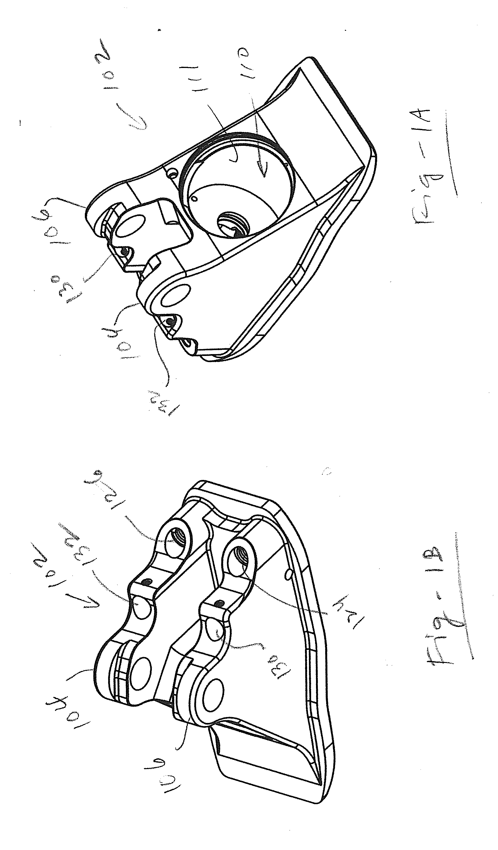
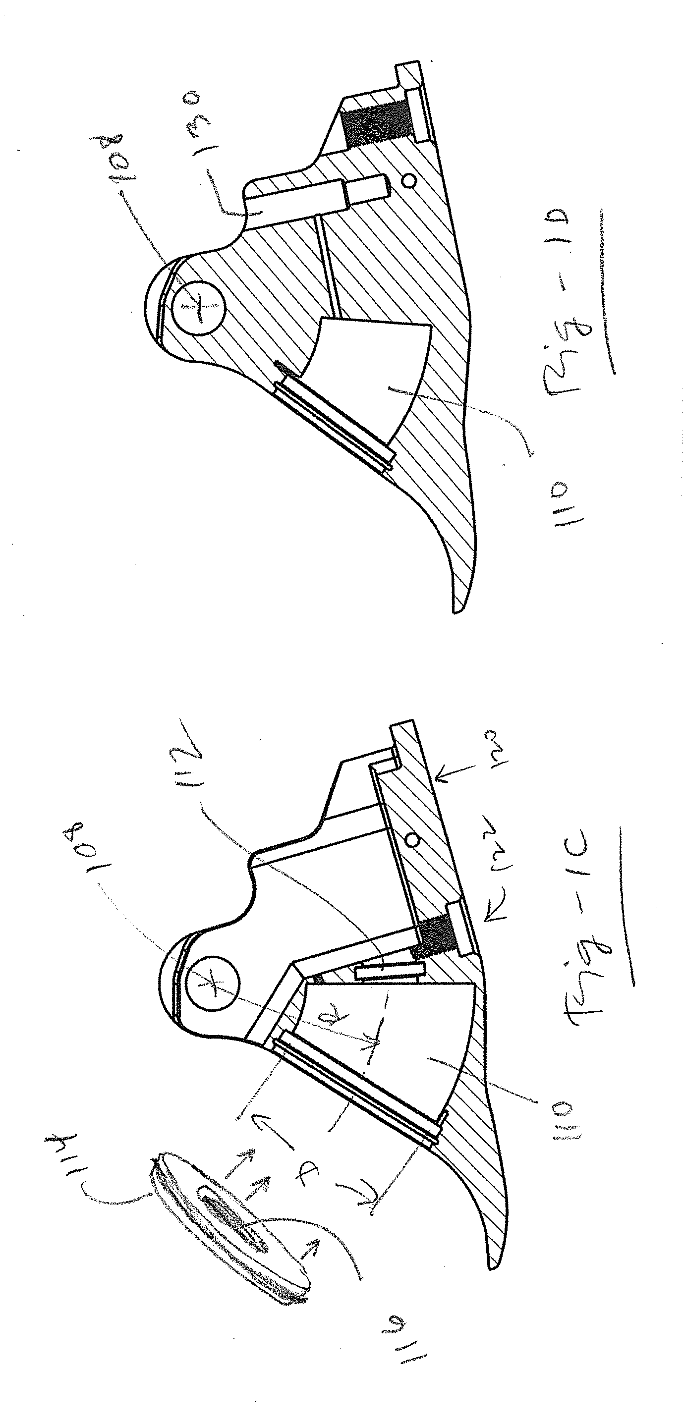
[0028]This invention resides in prosthetic joint and limb components that utilize a single, curved dampening cylinder to reduce component count and wear. In contrast to devices that rely on linear cylinders, the invention requires only one pivoting axis without the need for link members that rotate about additional axes. Such link members not only increase part count, the movement and potential play of the additional moving parts may result in added expense and increased wear.

[0029]In an embodiment associated with a prosthetic foot / ankle requires only three major components: a housing, an ankle component, and a piston component. These major components are in addition to a few minor components and the foot blade to which the housing attaches and the plyon to which the ankle component attaches. Foot blades and pylons are well known to those of skill in the art, and the invention is not limited in terms of which foot blades, pylons, or associated coupling mechanisms are used.

[0030]FIGS...


PUM


Abstract

Prosthetic joint and limb components utilize a single, curved dampening cylinder to reduce component count and wear. A prosthetic foot / ankle requires only three major components; namely, a housing adapted for coupling to a foot blade, an ankle component adapted for coupling to a pylon, and a piston that moves within a curved cylinder in the housing during ambulation. The ankle component is pivotally attached to the housing at the center of curvature of the cylinder. The piston defines front and rear, variable volume chambers in the cylinder. The chambers are in fluid communication with one another via a port, such that fluid is exchanged between the chambers through one-way check valves as the ankle pivots between plantarflexion and dorsiflexion. Fluid flow is independently adjustable to establish and maintain desired levels of dampening during plantarflexion and dorsiflexion, including different levels of dampening.

Description

FIELD OF THE INVENTION[0001]This invention relates generally to prosthetics and, in particular, to artificial joint and limbs utilizing curved dampening cylinders to reduce component count and wear.BACKGROUND OF THE INVENTION[0002]Those who wear prosthetic legs or feet confront several challenges to achieve natural and comfortable walking. These issues include changes in “effective heel height” and changes in the slope of the terrain encountered. Artificial limbs may function properly over smooth, horizontal surfaces or on slight inclines, but steeper inclines present problems, particularly when walking downhill. If the angle of the foot is not adequately adjustable, only the heel may make ground contact, making it difficult to accommodate the user's body weight and avoid buckling of the knee. For this reason, many prosthesis wearers often choose to walk sideways when walking downhill.[0003]Manual, mechanical adjustments are often difficult to set or calibrate, and do not automatic ...

Claims


Application Information

Patent Timeline
IPC IPC(8): A61F2/66
CPCA61F2/6607A61F2/68A61F2002/5006A61F2/66A61F2002/6614A61F2/74A61F2/748
Inventor TASZREAK, AARON
Owner COLLEGE PARK IND INC
Why Eureka
Eureka Blog
Learn More