
Joint lock ring system for lined pipes

a technology of locking rings and pipes, applied in the direction of pipes, pipe elements, mechanical equipment, etc., can solve the problems of affecting the quality of welded joints, weakening of cement or rubber during root passes, and contamination of welding, so as to achieve the effect of reducing the cost of materials

Active Publication Date: 2014-09-11
RABER ROBERT
View PDF31 Cites 5 Cited by
  • Summary
  • Abstract
  • Description
  • Claims
  • Application Information

AI Technical Summary

Benefits of technology

The present invention provides a method for connecting two lined pipes by inserting rings into the ends of the pipes and welding them together. The rings form a tight seal against the interior wall of the pipes, ensuring a secure and effective connection. The method may be enhanced by using a two-piece clamp to hold the rings in place during the welding process. The technical effect of this invention is a reliable and effective way to connect lined pipes in a particularly secure and efficient manner.

Problems solved by technology

One of the struggles that currently exists with pipes having internal cement or rubber linings is obtaining quality welds when connecting two pieces of beveled end steel cement-lined or rubber-lined, pipe.
Currently when two sections of pipe are joined together, beveled end against beveled end, and the initial weld pass (referred to as the “root pass”) directly contacts the cement or rubber lining, resulting in both contamination of the welding and weakening of the cement or rubber during the root pass.
Also this joint type does not allow a quality mechanical or nondestructive test of the completed welded joint.
Such a solution results in about a 20% or greater increase in the cost of materials.

Method used


Image

  • Joint lock ring system for lined pipes
  • Joint lock ring system for lined pipes
  • Joint lock ring system for lined pipes

Examples


Embodiment Construction

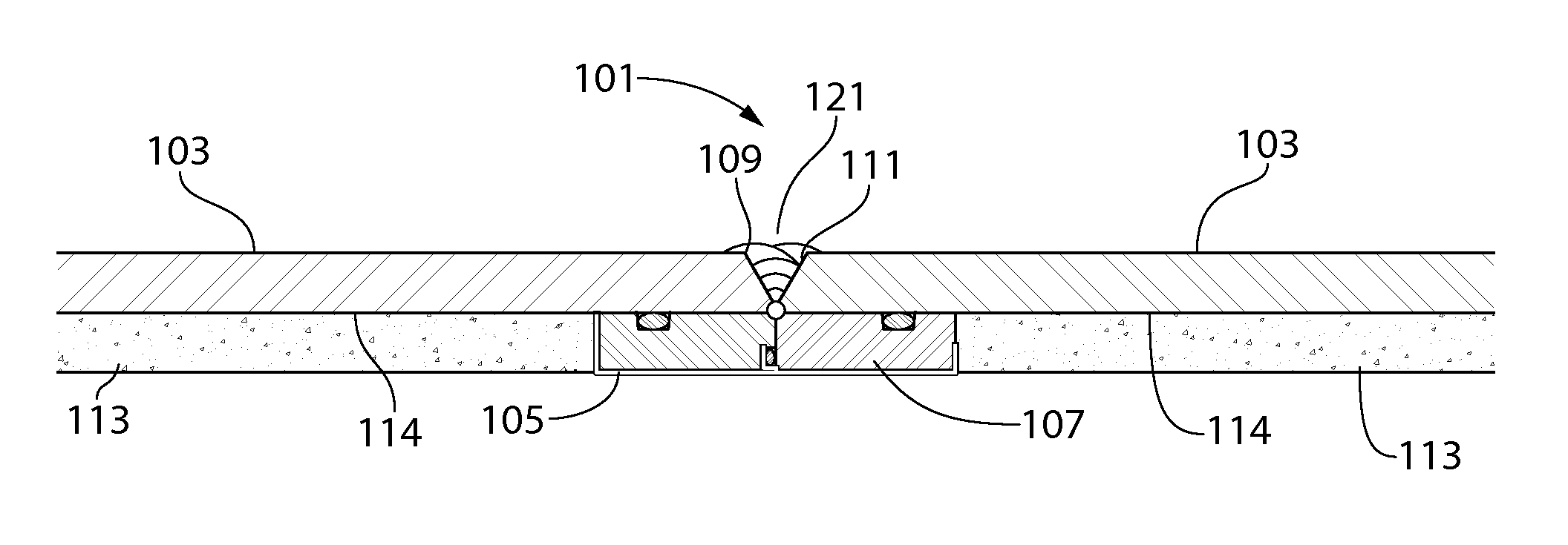
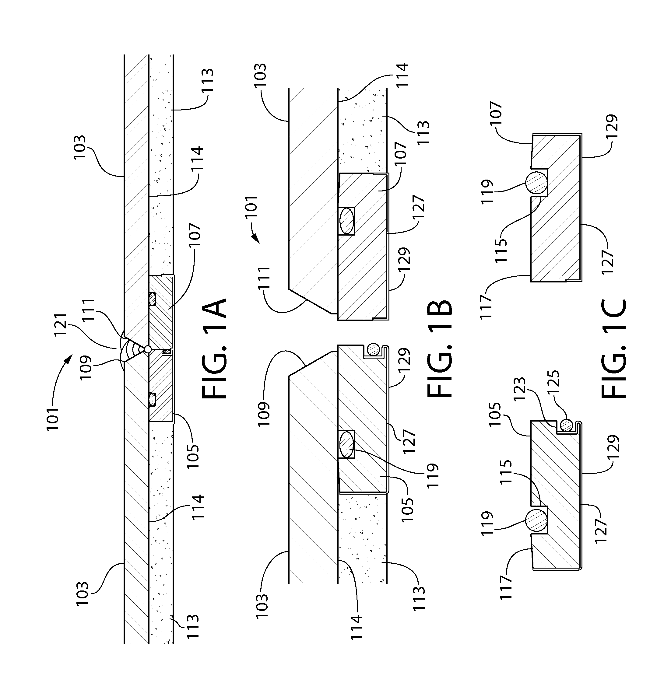
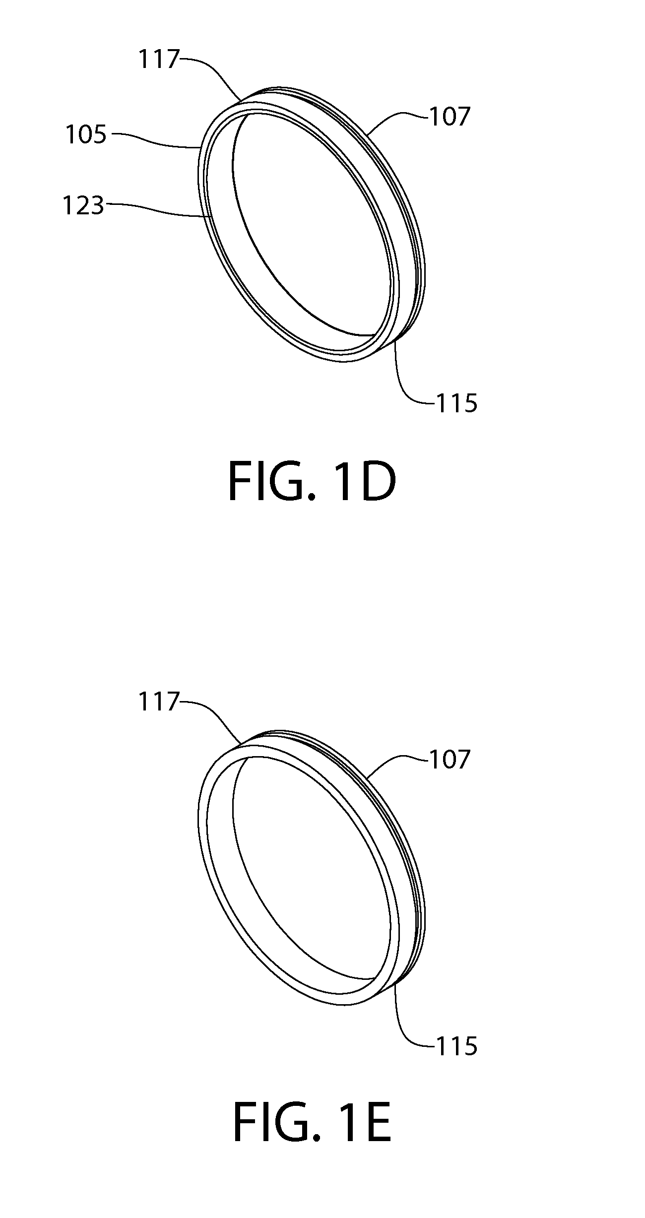
[0022]Turning in detail to the drawings, FIGS. 1A-E illustrate a joint lock ring system 101 suitable for use with a cement lined pipe 103. A cement lined pipe is described herein as an exemplified embodiment, and those of skill in the art will recognize that the same system may he used with any type of lined pipe, whether the lining be formed by cement, rubber, or any other materials. Thus, it is to be understood that The system includes two rings 105, 107, each inserted into the respective ends 109, 111 of the cement lined pipes 103, each ring being flush with the respective end of the pipe. The cement lining 113 lines the inner wall 114 of the pipes 103 between the rings 105, 107. Each ring 105, 107 is preferably formed from carbon steel, and preferably of the same steel grade and properties as the pipe, that is rolled to a specified diameter and machined to a specified tolerance. The diameter and tolerance are a matter of design choice, depending upon the size and wall thickness ...


PUM


Abstract

A joint ring, system for lined pipes includes a first pipe and a second pipe joined end-to-end, each pipe having an interior lining covering substantially all of an interior wall of the respective pipe. A first ring is disposed within and substantially flush with the joined end of the first pipe, and a second ring is disposed within and substantially flush with the joined end of the second pipe. The first ring is configured to create a first circumferential pressure seal against the interior wall of the first pipe, and the second ring is configured to create a second circumferential pressure seal against the interior wall of the second pipe. At least one of the first ring and the second ring is configured to create a pipe joint pressure seal against the other ring.

Description

CROSS-REFERENCE TO RELATED APPLICATIONS[0001]Priority is claimed to U.S. provisional application No. 61 / 775,749, filed Mar. 11, 2013, the disclosure of which is incorporated herein by reference in its entirety.FIELD OF THE INVENTION[0002]The field of the present invention is systems and methods for joining lined pipes, and particularly cement or rubber lined pipes.BACKGROUND OF THE INVENTION[0003]Within industries that use lined pipes, among winch is the mining industry, steel pipe is manufactured and may he installed for multiple purposes. Steel pipe can be connected or joined in a variety of ways depending on the application and design requirements. One of the struggles that currently exists with pipes having internal cement or rubber linings is obtaining quality welds when connecting two pieces of beveled end steel cement-lined or rubber-lined, pipe. Currently when two sections of pipe are joined together, beveled end against beveled end, and the initial weld pass (referred to as...

Claims


Application Information

Patent Timeline
IPC IPC(8): F16L13/02
CPCF16L13/0263F16L13/0227
Inventor RABER, ROBERT P.
Owner RABER ROBERT
Learn More