Power feeding device, power receiving device, and wireless power transmission device
a technology of power receiving device and wireless power transmission device, which is applied in the direction of transformers, inductances, transportation and packaging, etc., can solve the problems of increasing the number of wires and the number of control devices, increasing the size of devices, and complicated circuits, so as to suppress the increase in the size of equipment and improving the convenience of users
- Summary
- Abstract
- Description
- Claims
- Application Information
AI Technical Summary
Benefits of technology
Problems solved by technology
Method used
Image

Examples
first embodiment
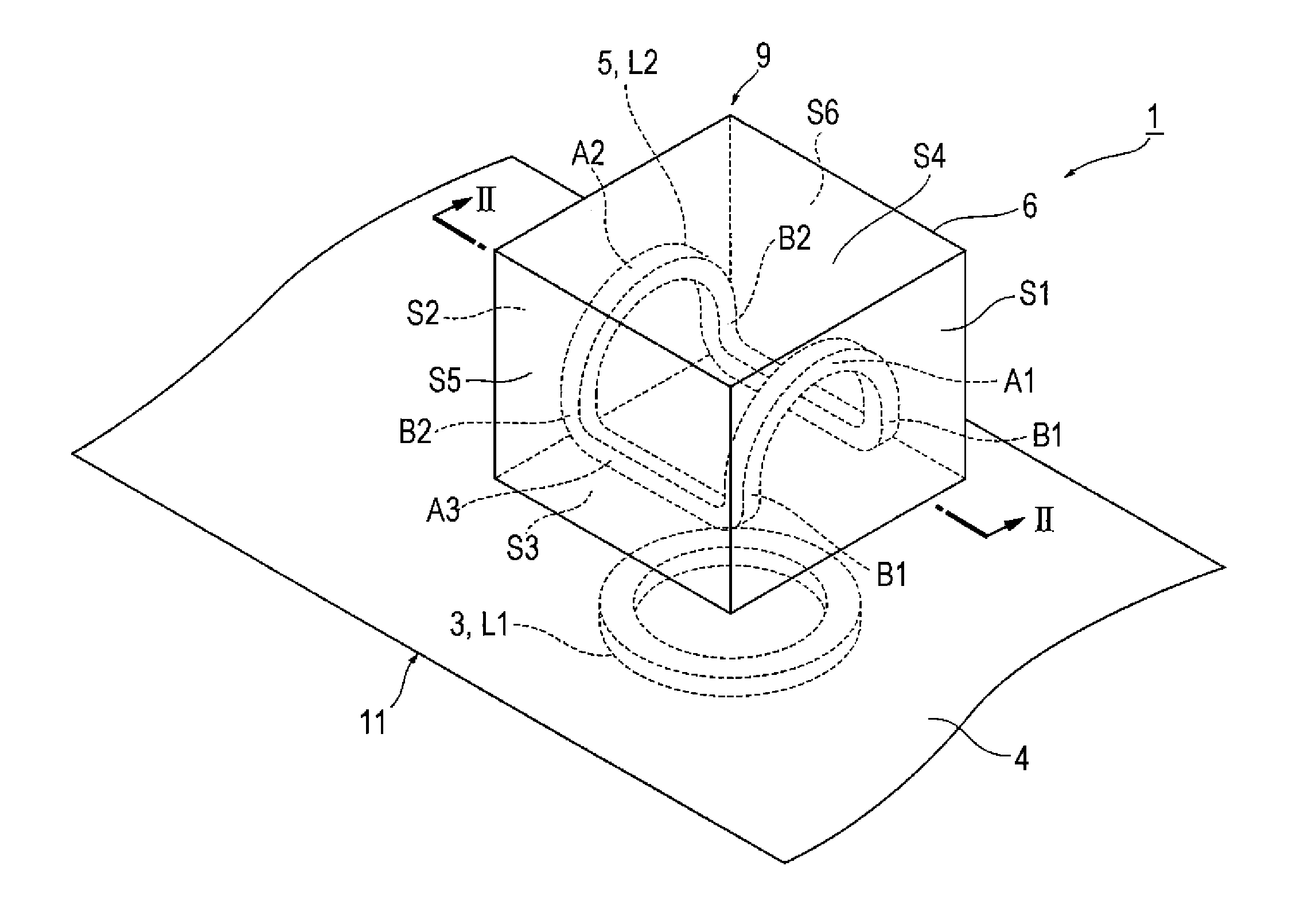
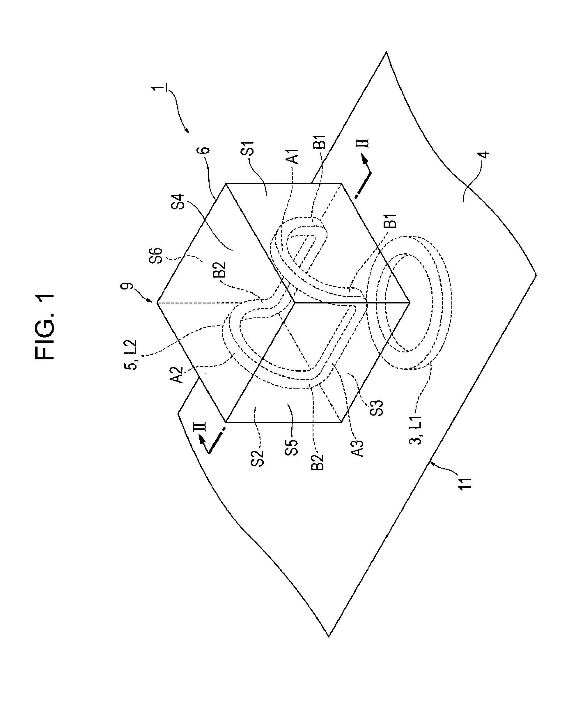
[0049]FIG. 1 is a perspective view of a wireless power transmission device according to a first embodiment, and FIG. 2 is a cross-sectional view taken along a cutting line II-II of the wireless power transmission device according to the first embodiment of the present invention. The wireless power transmission device 1 according to the first embodiment, illustrated in FIGS. 1 and 2 includes a power receiving device 9 according to the present invention and a power feeding device 11. The power receiving device 9 has a power receiving device main body 6 and a power receiving unit 5, and the power feeding device 11 has a power feeding device main body 4 and a power feeding unit 3, respectively. The power receiving unit 5 is constructed of a secondary coil L2, and the power feeding unit 3 is constructed of a primary coil L1. By the secondary coil L2 and the primary coil L1 being electromagnetically coupled, power is transmitted wirelessly from the power feeding device 11 to the power rec...
second embodiment
[0057]FIG. 4 is a perspective view of a wireless power transmission device according to a second embodiment of the present invention, and FIG. 5 is a cross-sectional view taken along a cutting line V-V of the wireless power transmission device according to the second embodiment of the present invention. The wireless power transmission device 40 according to the second embodiment, illustrated in FIGS. 4 and 5 includes a power receiving device 9 according to the present invention and a power feeding device 11.
[0058]As illustrated in FIGS. 4 and 5, the outer shape of the power receiving device main body 6 is a rectangular parallelepiped having six faces. The power receiving device 9 has a power receiving device main body 6, and a power receiving unit package 10 in which the secondary coil L2 is packaged by a resin 8 or the like. In the present embodiment, the U-shaped power receiving unit package 10 is attached to the outside of the power receiving device main body 6. The secondary coi...
third embodiment
[0072]FIG. 7 is a perspective view of a wireless power transmission device according to a third embodiment of the present invention. A wireless power transmission device 70 according to the third embodiment, as illustrated in FIG. 7 is obtained by changing the shape and the number of the power receiving unit 5 of the power receiving device 9 in the first embodiment.
[0073]Two secondary coils L2 are incorporated into the power receiving device 9. Similarly to the first embodiment, the secondary coil L2 may include a magnetic body, and may be packaged by a resin. The secondary coil L2 constituting a power receiving unit 5a on one side includes portions A1, A4, and A5 respectively located along three faces S1, S4, and S5 which form the outer shape of the power receiving device 9 and are not parallel to each other, and the secondary coil L2 constituting a power receiving unit 5b on the other side includes portions A2, A3, and A6 respectively located along three faces S2, S3, and S6 which...
PUM
 Abstract
Description
Claims
Application Information
 - R&D
- Intellectual Property
- Life Sciences
- Materials
- Tech Scout
- Unparalleled Data Quality
- Higher Quality Content
- 60% Fewer Hallucinations
Browse by: Latest US Patents, China's latest patents, Technical Efficacy Thesaurus, Application Domain, Technology Topic, Popular Technical Reports.
© 2025 PatSnap. All rights reserved.Legal|Privacy policy|Modern Slavery Act Transparency Statement|Sitemap|About US| Contact US: help@patsnap.com