Housing for Accommodating an Electronic Circuit

a technology for electronic circuits and housings, applied in the field of housings, can solve the problems of air exchange with the environment, suitability for slight condensation of moisture, etc., and achieve the effect of reducing air volume and air volume inside the interior

Active Publication Date: 2014-09-11
EBM PAPST MULFINGEN GMBH & CO KG
View PDF6 Cites 6 Cited by
  • Summary
  • Abstract
  • Description
  • Claims
  • Application Information

AI Technical Summary

Benefits of technology

[0009]Since according to the invention only a very small volume of air is present inside the interior, only a minimal amount of moisture is also enclosed in this air volume. As a result, the maximum amount of moisture which can be present in the air volume cannot lead to damage of the electronic components. In order to the keep the air volume inside the interior as small as possible, it is furthermore inventively expedient, if volume elements are provided in the edge region of the circuit board on the side of the volume compensation element facing the circuit board, i.e. between the wall of the housing and the electronic components. It is inventively also optionally possible to provide an inlay component above the circuit board in the gap between the circuit board and the housing cover for reduction of air volume. Due to the inventive design, no further moisture can penetrate into the interior of the housing between the volume compensation element and the housing cover via volume compensation, whereby accumulation of moisture cannot occur, since no mass transport into the housing can occur. Furthermore, the inventive pressure equalization serves to clamp the sealing elements present, since internal and external pressure on the sealing elements compensate approximately equally. A complete sealing with respect to the external environment, i.e. atmosphere, is also provided by the inventive volume compensation element in the region of feed-throughs which for example serve for the feed-through of connecting pins or the like.

Problems solved by technology

This method, however, is only suitable for slight condensation of moisture.
It is further known that the electronic components are cast in a sealing compound (potting) which, however, entails disadvantages with respect to the thermo-mechanical forces arising, which act on the components and can damage them.
In this case there is the disadvantage that an exchange of air takes place with the environment, and penetration of moisture into the housing is thereby possible.

Method used


Image

  • Housing for Accommodating an Electronic Circuit
  • Housing for Accommodating an Electronic Circuit
  • Housing for Accommodating an Electronic Circuit

Examples


Embodiment Construction

[0018]In FIGS. 1 to 7, identical parts or functionally identical parts are indicated by the same reference numbers. Insofar as specific features of the inventive housing or volume compensation element or their components, which features are described and / or inferable from the drawings, are described only in the context of an exemplary embodiment, according to the invention these features are also significant independent of this exemplary embodiment as individual features or, however, also in combination with other features of the exemplary embodiment and are claimed as belonging to the invention.

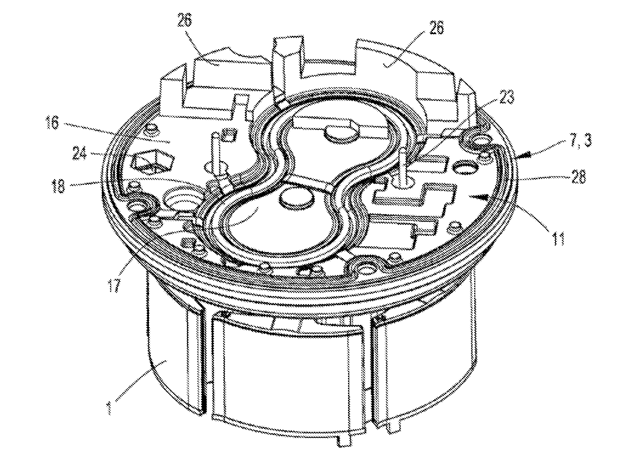
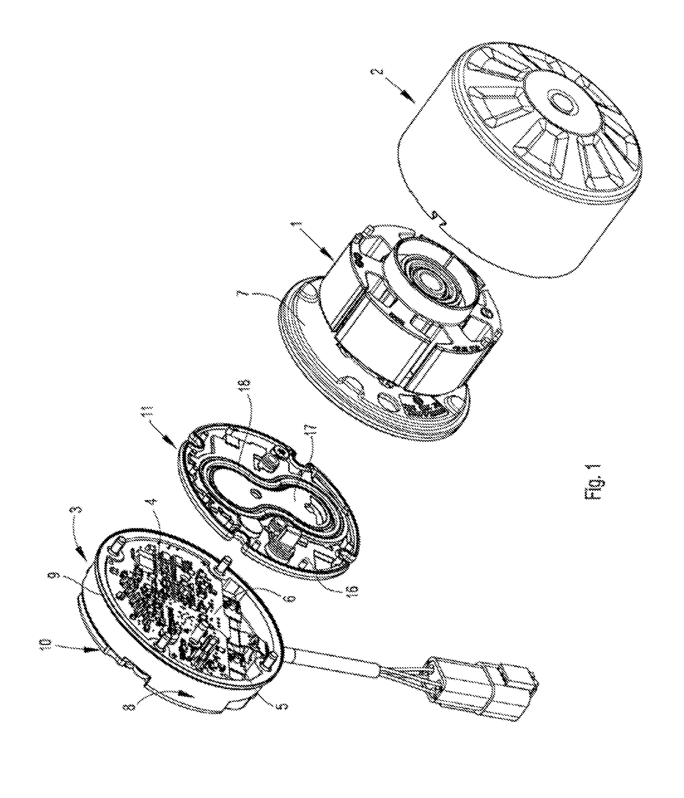
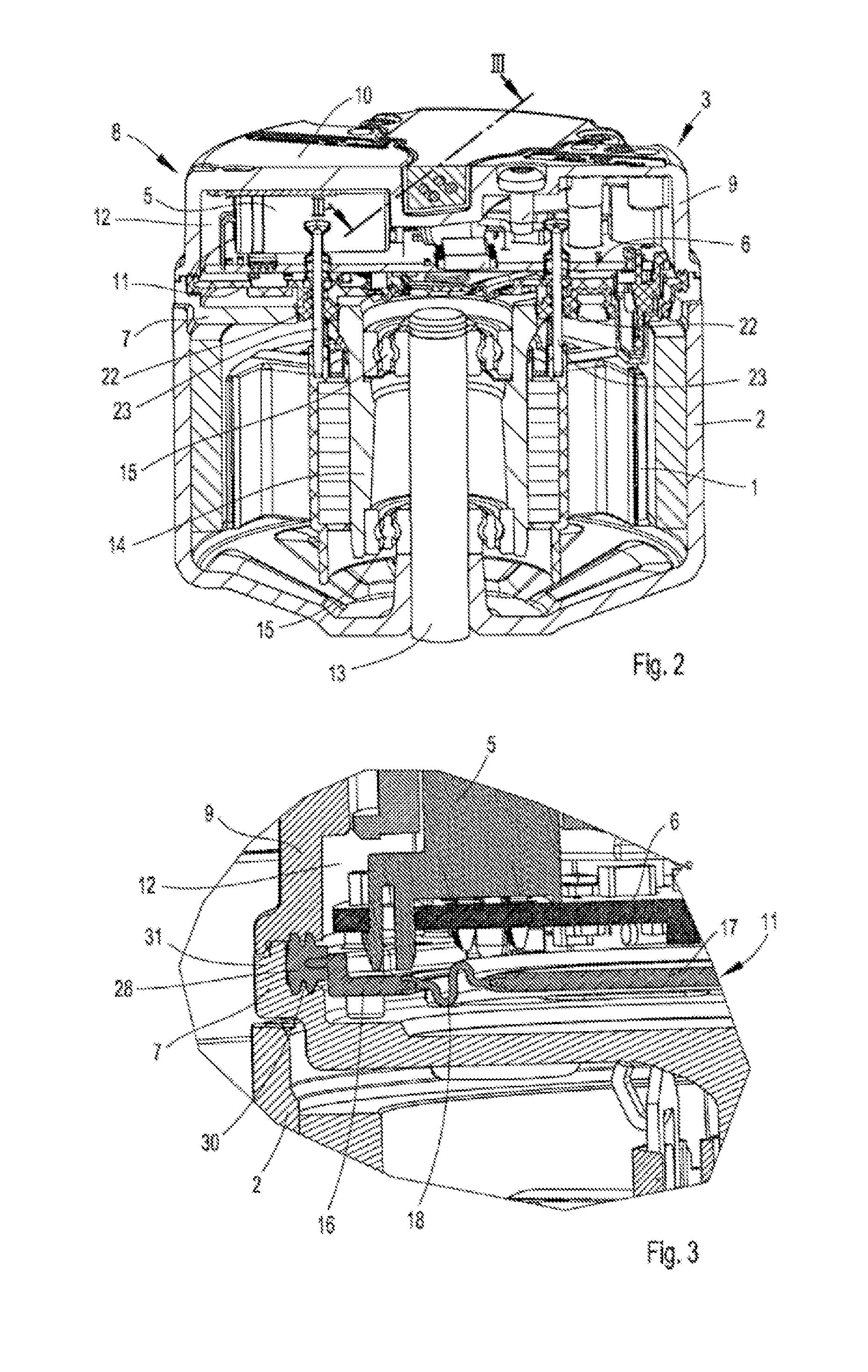
[0019]FIG. 1 shows a perspective exploded view of an electric motor, formed of a stator 1 and a rotor 2 as well as an electronics housing 3, wherein an electronic circuit 4 made of components 5 and a circuit board 6 is disposed. The electronics housing 3 is formed from a carrier plate 7 and a housing cover 8. In the illustrated exemplary embodiment the carrier plate 7 is formed as a stator f...


PUM


Abstract

A housing for receiving an electronic circuit (4) having a plurality of components (5) having a carrier plate (7) and a housing cover (8) including a circumferentially enclosing wall (9) on the carrier plate (7) and a cover part (10) on the wall (9), which cover part (10) lies opposite the carrier plate (7). A volume compensation element (11) is attached on the carrier plate (7) in an interior (12) of the housing cover (8) which is enclosed in a pressure-tight manner from an external atmosphere. The volume compensation element (11) is elastically formed providing a variable volume for compensation of pressure fluctuations in the interior (12), which variable volume occurs with a change in position of the volume compensation element (11) relative to the carrier plate (7). A gap between the volume compensation element (11) and the carrier plate (7) is connected to the external atmosphere.

Description

CROSS REFERENCE TO RELATED APPLICATION[0001]This application claims priority to PCT / EP2011 / 071342, filed on Nov. 30, 2011.FIELD OF THE INVENTION[0002]The present invention relates to a housing to receive an electronic circuit made of a plurality of components, comprised of a carrier plate and a housing cover, including a circumferentially enclosing wall disposed on the carrier plate and a cover part disposed on the wall, lying opposite the carrier plate.BACKGROUND[0003]Electronic components must generally be protected from moisture. It is therefore known that one e.g. applies a moisture-proof lacquer on a circuit board of an electronic circuit and on the components attached to the circuit board. This method, however, is only suitable for slight condensation of moisture.[0004]It is further known that the electronic components are cast in a sealing compound (potting) which, however, entails disadvantages with respect to the thermo-mechanical forces arising, which act on the components...

Claims


Application Information

Patent Timeline
Patent Type & Authority Applications(United States)
IPC IPC(8): H05K5/06H02K5/10
CPCH02K5/10H05K5/068H02J3/24H02J3/32H02J7/00H02J7/0013
Inventor SAUER, THOMASBEST, DIETERMATTER, WALTERBERBERICH, JOACHIM
Owner EBM PAPST MULFINGEN GMBH & CO KG
Why Eureka
Try Eureka