Liquid discharging apparatus and method of cleaning discharge head

a liquid discharge head and liquid discharge technology, applied in the direction of printing mechanisms, power drive mechanisms, printing, etc., can solve the problems of deterioration of image quality, insufficient spread of cleaning liquid, and inability to perform effective cleaning

Active Publication Date: 2014-09-11
SEIKO EPSON CORP
View PDF6 Cites 18 Cited by
  • Summary
  • Abstract
  • Description
  • Claims
  • Application Information

AI Technical Summary

Benefits of technology

[0016]As above, when the depression (groove portion) is present on the nozzle forming surface and when the wiping is performed under the reciprocating wiping control, there is a case in which an extraneous substance which is scraped off the nozzle forming surface comes in the depression together with the cleaning liquid. If time elapses in such a state, the extraneous substance comes deep in the depression due to capillary action depending on a shape of the depression, and thus it is difficult to remove the extraneous substance from the depression. Here, as described above, when the reciprocating operation is performed such that the wiping member passes through above the depression, it is possible to perform suitable cleaning by scraping the extraneous substance from the depression together with the cleaning liquid before the extraneous substance comes deep in the depression.

Problems solved by technology

If the liquid adheres to the nozzle forming surface, there is a problem in that the liquid is not appropriately discharged from the nozzles, thereby causing deterioration of image quality.
However, in the head cleaning mechanism disclosed in JP-A-2009-233896, after the cleaning liquid is ejected onto the nozzle forming surface, the wiping member wipes the nozzle forming surface one time in one direction, with the result that the cleaning liquid is not sufficiently spread thereon, and thus there is a problem in that effective cleaning is not performed.
If time elapses in such a state, the extraneous substance comes deep in the depression due to capillary action depending on a shape of the depression, and thus it is difficult to remove the extraneous substance from the depression.

Method used


Image

  • Liquid discharging apparatus and method of cleaning discharge head
  • Liquid discharging apparatus and method of cleaning discharge head
  • Liquid discharging apparatus and method of cleaning discharge head

Examples


Embodiment Construction

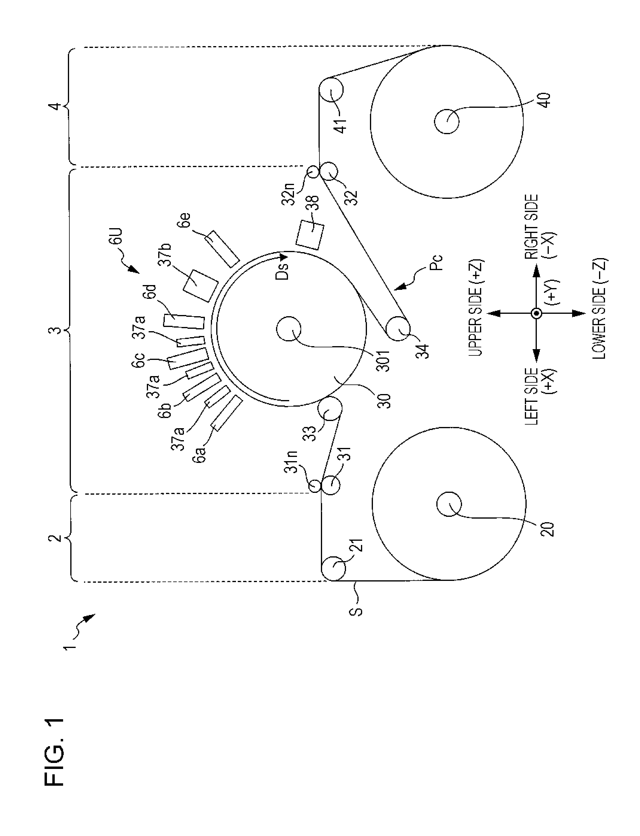
[0027]Hereinafter, the configuration of a printer to which the invention can be applied will be described with reference to the accompanying drawings. FIG. 1 is a front view illustrating the configuration of a printer to which the invention can be applied. Meanwhile, in the drawings below, a 3-dimensional coordinate system which corresponds to the horizontal direction X, the front-back direction Y, and the vertical direction Z of a printer 1 is used if necessary for clarity arrangement relationship between the respective units of the printer 1.

[0028]As shown in FIG. 1, in the printer 1, a feeding section 2, a processing section 3 and a winding section 4 are arranged in the horizontal direction. The feeding section 2 and the winding section 4 include a feeding shaft 20 and a winding shaft 40, respectively. Further, both ends of a sheet S (web) are wound around the feeding section 2 and the winding section 4 in a roll shape, and are stretched therebetween. After the sheet S is transpo...


PUM


Abstract

There is provided a liquid discharging apparatus which includes a discharge head that includes a nozzle forming surface on which nozzles for discharging liquid are formed; a wiping member that performs wiping by relatively moving on the nozzle forming surface while abutting on the nozzle forming surface; a cleaning liquid supply unit that supplies cleaning liquid provided for the wiping; and a control unit that performs reciprocating wiping control which performs the wiping by causing the wiping member for holding the cleaning liquid supplied from the cleaning liquid supply unit to perform a reciprocating operation in which, after relative movement is performed in a first direction along the nozzle forming surface, relative movement is performed in a second direction which is opposite to the first direction.

Description

BACKGROUND[0001]1. Technical Field[0002]The present invention relates to a technology that cleans the nozzle forming surface of a discharge head which discharges liquid, and, in particular, to a technology that performs wiping with a wiping member on the nozzle forming surface using cleaning liquid.[0003]2. Related Art[0004]In the related art, a liquid discharging apparatus, such as an ink jet printer, which discharges liquid, such as ink or the like, from the nozzles of a discharge head is known. In such an apparatus, there is a case in which the liquid discharged from the nozzles adheres to the nozzle forming surface of the discharge head. If the liquid adheres to the nozzle forming surface, there is a problem in that the liquid is not appropriately discharged from the nozzles, thereby causing deterioration of image quality. Here, various technologies for removing liquid which adheres to the nozzle forming surface of a discharge head are proposed.[0005]For example, a head cleaning...

Claims


Application Information

Patent Timeline
Patent Type & Authority Applications(United States)
IPC IPC(8): B41J2/165
CPCB41J2/16535B41J2/16552B41J2/16588B41J2025/008
Inventor KOBAYASHI, YOSHIHIROKUMAGAI, TOSHIOMASUDA, NORIHIROONODERA, KATSUYOSHI
Owner SEIKO EPSON CORP
Why Eureka
Try Eureka