Automatic cleaning machine of delivery pump pipe

A technology for conveying pumps and cleaning machines, which is applied in the field of automatic cleaning machines for conveying pump pipes, and achieves the effect of simple structure and convenient use

Inactive Publication Date: 2013-09-25
DONGHUA CONSTR COMPANY LTD OF YANKUANG GRP
View PDF9 Cites 15 Cited by
  • Summary
  • Abstract
  • Description
  • Claims
  • Application Information

AI Technical Summary

Problems solved by technology

Steel wire brushes can be made from waste steel wire rope ends

Method used


Image

  • Automatic cleaning machine of delivery pump pipe
  • Automatic cleaning machine of delivery pump pipe
  • Automatic cleaning machine of delivery pump pipe

Examples


Embodiment approach 1

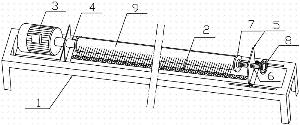
[0020] Implementation mode one: if figure 1 As shown, the automatic cleaning machine for conveying pump tubes includes a base frame 1, a steel wire brush 2 and a pump tube driving motor 3, wherein one end of the base frame 1 is provided with a bearing seat and a bearing, and a rotating shaft 4 is arranged inside the bearing, and is driven by the pump tube Motor 3 drives, and base frame 1 other end is provided with support member 5, and this support member 5 is fixed with screw nut or has the screw nut through hole, and screw nut or screw nut through hole is provided with screw mandrel 6, and this screw mandrel 6 The inner end is fixed with a top plate 7 through bearings, and the other end of the screw rod 6 is provided with an adjustment handwheel 8 (or rocker), and the axis of the screw rod 6 coincides with the axis of the rotating shaft 4 . The steel wire brush 2 is longitudinally strip-shaped, arranged on one side of the base frame 1, and abuts against the delivery pump pip...

Embodiment approach 2

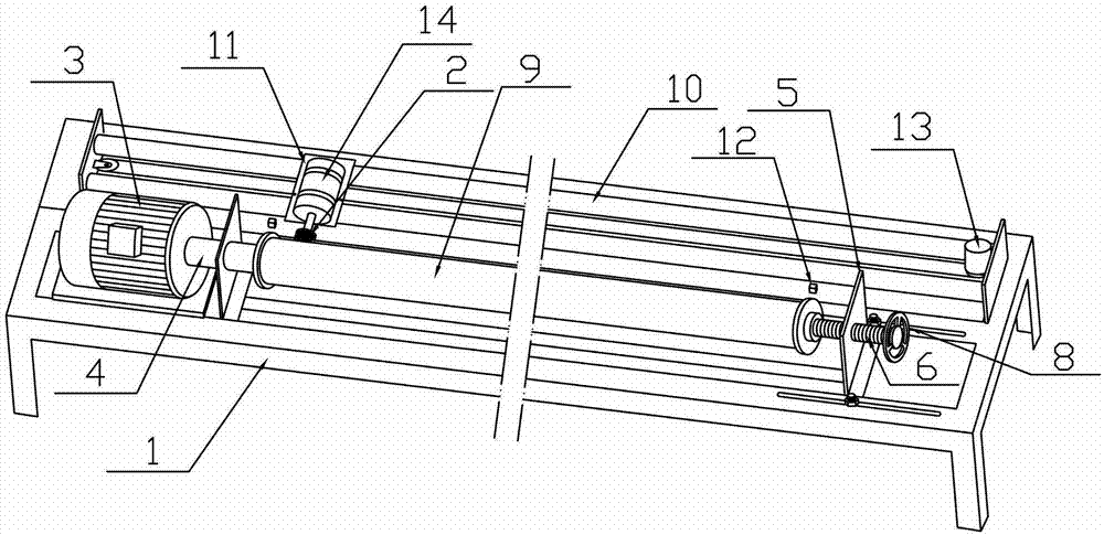
[0022] Implementation mode two: if figure 2 As shown: the delivery pump pipe automatic cleaning machine includes a track 10, the track 10 is parallel to the axis of the screw mandrel 6, and is provided with a pulley 11, the pulley 11 is equipped with a pulley drive mechanism, and the drive mechanism is a pulley block drive mechanism ( Certainly also can select screw mandrel screw nut driving mechanism or rack and pinion driving mechanism, omission), described steel wire brush 2 just is arranged on the described pulley 11, and the stroke end point and starting point of pulley 11 are all provided with limit limit switch 12. The limit limit switch 12 controls the drive motor 13 of the pulley drive mechanism through the reversing circuit.

[0023] Described steel wire brush 2 is equipped with a brush body rotation motor 14, and this brush body rotation motor 14 is fixed on the described pulley 11 by a hand-operated screw rod, is convenient to adjust the distance between steel wir...

Embodiment approach 3

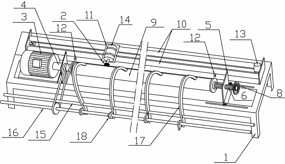
[0024] Implementation mode three: if image 3 Shown: described pedestal 1 is provided with support bar 15 and cam bar 16, and support bar 15 is provided with a plurality of lever hammers 17, and the middle section of each lever hammer 17 is sleeved on support bar 15, and the front end of lever hammer 17 The hammer head extends and presses on the delivery pump pipe 9 to be cleaned. The hammer handle at the rear end of the lever hammer extends to the cam lever 16. The cam lever 16 is provided with a plurality of cams 18, and the cams correspond to the lever hammer 17 one by one. In cooperation, the cam lever 16 is driven by the pump tube drive motor 3 .

[0025] In order to ensure safety, a protective cover should be added outside the steel wire brush 2, the rotating mechanism and the transmission mechanism, the figure is omitted.


PUM


Abstract

The invention relates to an automatic cleaning machine of a delivery pump pipe. A specialized mechanical device for cleaning the delivery pump pipe is not available in the current market, resulting in great inconvenience. Therefore, automatic cleaning machine comprises a base frame, a steel wire brush and a pump pipe driving motor, wherein a bearing support and a bearing are arranged at one end of the base frame; a rotating shaft is arranged in the bearing, and is driven by the pump pipe driving motor; a support piece is arranged at the other end of the base frame; a nut is fixed on the support piece, or a nut through hole is formed in the support piece; a screw rod is arranged in the nut or the nut through hole; an inner end of the screw rod is fixed with a top plate through the bearing; an adjusting hand wheel or a rocking handle is arranged at the other end of the screw rod; the axial line of the screw rod and the axial line of the rotating shaft coincide. The automatic cleaning machine has the advantages of simple structure and convenience in use, and is suitable for cleaning various concrete delivery pump pipes.

Description

technical field [0001] The invention relates to an automatic cleaning machine for conveying pump pipes. Background technique [0002] The concrete delivery pump can directly deliver concrete to the working surface through the delivery pump pipe, which greatly saves manpower and material resources and improves work efficiency. After use, the pump pipe needs to be cleaned of residual concrete on the inner and outer walls of the pump pipe in time to prevent it from solidifying. [0003] At present, there is no special mechanical equipment on the market to clean the delivery pump pipe. The usual cleaning method is to put the sponge ball or rubber piston into the pump pipe and use water pressure to clean the inside of the pump pipe after the concrete has been conveyed. Although the inside of the pump pipe after cleaning is clean, the outer surface still has concrete and has solidified; due to poor storage at the construction site, the inside of the pump pipe after cleaning may s...

Claims


Application Information

Patent Timeline
Patent Type & Authority Applications(China)
IPC IPC(8): B08B9/023
Inventor 柴国胜郭凯李海冬王庆林
Owner DONGHUA CONSTR COMPANY LTD OF YANKUANG GRP
Why Eureka
Try Eureka