

System and method for determining vital sign information
- Summary
- Abstract
- Description
- Claims
- Application Information
AI Technical Summary
Benefits of technology
Problems solved by technology
Method used
Image

Examples
first embodiment
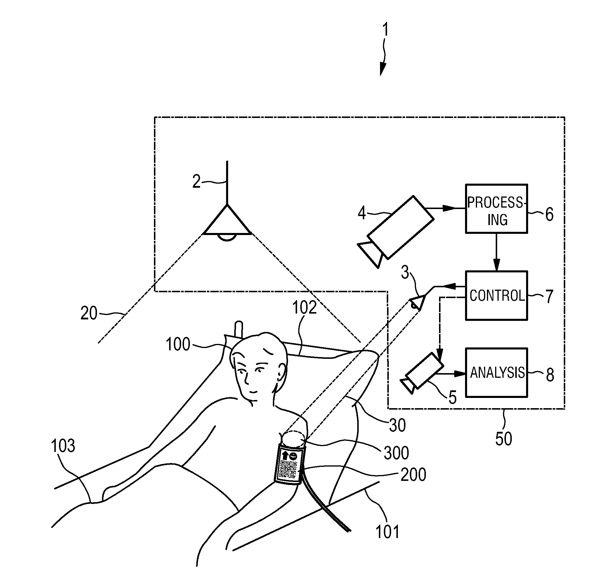
[0060]FIG. 1 shows the system 1 for determining vital sign information of a subject according to the present invention. The subject 100, in this example a patient, lies in a bed 101, wherein the head of the subject 100 is located on a pillow 102 and the subject 100 is covered with a blanket 103. The system 1 comprises an (optional) first illumination unit 2 for illuminating the subject 100 with invisible radiation 20 in a first frequency range and a second illumination unit 3 for illuminating a region of interest (ROI) 300 of the subject 100 with visible light 30 in a second frequency range. A first detection unit 4 is provided for receiving first radiation emitted and / or reflected from the subject 100 in said first frequency range, and a second detection unit 5 is provided for receiving second radiation emitted and / or reflected from at least said ROI 300 of the subject 100 in said second frequency range.
[0061]The first illumination unit 2 and the second illumination unit 3 are for ...
fourth embodiment
[0094]It shall be noted that the fourth embodiment illustrated in FIGS. 8 to 10 is not limited to the determination of SPO2, but can also be used for determining other vital signs.
[0095]The present invention thus provides that accurate and reliable vital sign measurements can be made in darkness or low-light conditions with causing any trouble to the subject himself, in particular a person or animal, and other persons nearby.
[0096]The measured vital sign information can be automatically provided to a doctor or to a hospital computer system. The proposed system for determining a vital sign of a subject is intended for use in a hospital, at a clinic, at a doctor or for monitoring patients at home. The system can, for instance, be installed in a hospital room but also in an incubator, e.g., in a neonatal ICU (NICU), e.g. for measurement of SpO2 for NICU. But other (not necessarily medical) applications of the invention are generally possible.
[0097]The contactless monitoring is assumed ...
PUM
 Abstract
Description
Claims
Application Information