System and Method for Uplink Grant-Free Transmission Scheme

Active Publication Date: 2014-09-11
HUAWEI TECH CO LTD
View PDF10 Cites 320 Cited by
  • Summary
  • Abstract
  • Description
  • Claims
  • Application Information

AI Technical Summary

Benefits of technology

[0004]These and other problems are generally solved or circumvented, and technical advantages are generally achieved, by p

Problems solved by technology

An issue with this approach is that the signaling resource overhead for the scheduling/grant mechanism can be quite large, especially in cases wh

Method used


Image

  • System and Method for Uplink Grant-Free Transmission Scheme
  • System and Method for Uplink Grant-Free Transmission Scheme
  • System and Method for Uplink Grant-Free Transmission Scheme

Examples


Embodiment Construction

[0019]The making and using of embodiments are discussed in detail below. It should be appreciated, however, that the present invention provides many applicable inventive concepts that can be embodied in a wide variety of specific contexts. The specific embodiments discussed are merely illustrative of specific ways to make and use the invention, and do not limit the scope of the invention.

[0020]Various embodiments are described with respect to a specific context, namely a LTE wireless communication network. Various embodiments may also be applied, however, to other wireless networks such as a worldwide interoperability for microwave access (WiMAX) network.

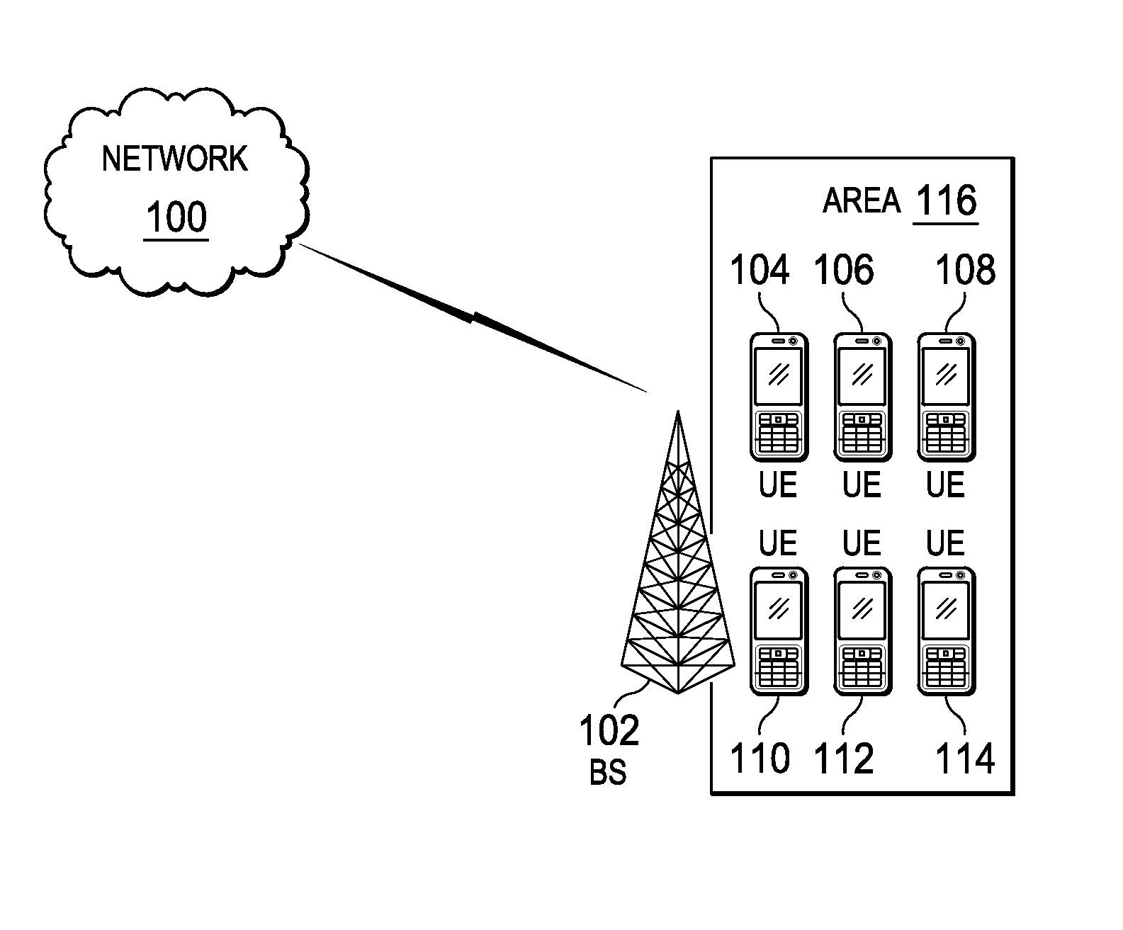
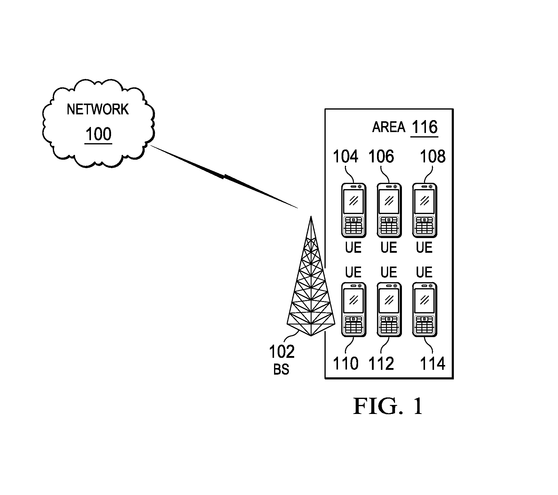
[0021]FIG. 1 illustrates a block diagram of a network 100 according to various embodiments. A base station (BS) 102 manages uplink and downlink communications for various UEs 104-114 within its coverage area 116. BS 102 may alternatively be referred to as a cell tower, an eNodeB, an access network, and the like. BS 102 may support t...


PUM


Abstract

A method embodiment includes implementing, by a base station (BS), a grant-free uplink transmission scheme. The grant-free uplink transmission scheme defines a first contention transmission unit (CTU) access region in a time-frequency domain, defines a plurality of CTUs, defines a default CTU mapping scheme by mapping at least some of the plurality of CTUs to the first CTU access region, and defines a default user equipment (UE) mapping scheme by defining rules for mapping a plurality of UEs to the plurality of CTUs.

Description

TECHNICAL FIELD[0001]The present invention relates to a system and method for wireless communications, and, in particular embodiments, to a system and method for uplink grant-free transmission scheme.BACKGROUND[0002]In a typical wireless network such as long-term evolution (LTE) network, the selection of shared data channels for uplink (UL) is scheduling / grant based, and the scheduling and grant mechanisms are controlled by a base station (BS) in a network. A user equipment (UE) sends an UL scheduling request to the base station. When the BS receives the scheduling request, the BS sends an UL grant to the UE indicating its UL resource allocation. The UE then transmits data on the granted resource.[0003]An issue with this approach is that the signaling resource overhead for the scheduling / grant mechanism can be quite large, especially in cases where the data transmitted is small. For example, for small packet transmissions of around 20 bytes each, the resources used by the scheduling...

Claims


Application Information

Patent Timeline
IPC IPC(8): H04W72/04
CPCH04W74/08H04W72/02H04L5/0005H04L5/0041H04L5/0048H04L1/1812H04W72/23H04W74/0833H04W74/0866H04L5/0033H04L1/0038H04L1/1861H04W72/1268H04W74/0825
Inventor KAR KIN AU, KELVINNIKOPOUR, HOSEINDJUKIC, PETARYI, ZHIHANGBAYESTEH, ALIREZAMA, JIANGLEIBALIGH, MOHAMMADHADIZHANG, LIQING
Owner HUAWEI TECH CO LTD
Why Eureka
Try Eureka