Structural connection mechanisms for providing discontinuous elastic behavior in structural framing systems

a structural framing system and discontinuous elastic technology, applied in the direction of rod connections, mechanical devices, shock-proofing, etc., can solve the problems of structural members deformed, structural misalignment, and structural structural members that are not stable, so as to and enhance the elastic characteristics of the structural frame and its response.

Active Publication Date: 2014-09-18
HAYES TIMOTHY A
View PDF13 Cites 14 Cited by
  • Summary
  • Abstract
  • Description
  • Claims
  • Application Information

AI Technical Summary

Benefits of technology

[0009]In accordance with one aspect of the invention, a structural frame for a building includes a plurality of first structural members and a plurality of second structural members coupled to the plurality of first structural members, with a discontinuous elastic zone being present at a location where a respective first structural member is coupled to a respective second structural member through which a load passes between the first and second structural members during a loading event. The structural frame also includes a plurality of discontinuous elastic zone connections configured to couple the plurality of first structural members to the plurality of second structural members, with the discontinuous elastic zone connections configured to enhance the elastic characteristics of the structural frame and of its response to transient loads. Each of the plurality of discontinuous elastic zone connections includes faying surfaces either rigidly connected to or formed as part of respective first and second structural members, with the faying surfaces opposing each other and either in contact with each other or separated by a compression element in an interstitial space between the opposing faying surfaces. Each of the plurality of discontinuous elastic zone connections also includes fastening devices configured to secure a respective first structural member to a respective second structural member and a compression element positioned on each fastening device, with the compression element comprising a singular component or plurality of deformable components in a stacked arrangement. The compression element is configured to act in combination with a respective fastening device so as to regulate movement of the faying surfaces relative to each other, and thus regulate the behavior of the discontinuous elastic zone connection resulting from loads applied by respective first and second structural members on opposing sides of a respective discontinuous elastic zone.
[0010]In accordance with another aspect of the invention, a structural frame for a building includes a plurality of vertically oriented columns configured to provide gravity and lateral load resisting support to the structural frame, a plurality of horizontally oriented beams coupled to the plurality of columns at a plurality of intersections, a plurality of beam-to-column discontinuous elastic zone connections configured to couple the plurality of vertically oriented columns to the plurality of horizontally oriented beams at the plurality of intersections, a plurality of braces positioned in frame bays designated to resist drift, and transfer shear to the base, formed by respective pairs of columns and beams each comprising a multi-piece brace having a plurality of brace portions, and a plurality of discontinuous elastic zone connections to couple the plurality of brace portions to each other, so as to enhance the elastic characteristics of the structural frame and its response to transient loads on the structural frame in discontinuous elastic zones through which a load passes during a loading event. Each of the plurality of discontinuous elastic zone connections comprises a plurality of connection mechanisms and a compression element positioned on each of the plurality of connection mechanisms and comprising single component or a plurality of deformable components in a parallel stack, a series stack, or a combination of parallel stacks and series stacks, wherein the compression element is configured to enhance the elastic characteristics of the structural frame and its response to transient and non-transient loads, and wherein the compression element is configured to provide elasticity and damping in the structural frame in response to transient loads and overloading applied to the structural frame.

Problems solved by technology

In the case of seismic loading, current codes allow drift that in many circumstances results in flexure of conventional rigid connections that exceeds the elastic limits of materials used to construct such conventional connections.
In the weak beam-strong column philosophy, it is presumed that seismic events that load structural components, most notably beams and braces, beyond their elastic capacity, i.e. plastic inelastic behavior, will result in a structure that is misaligned, exhibiting deformed structural members following such an event.
It is further presumed that such misalignment and deformation may be significant enough to render the building uninhabitable and in some cases unrepairable.
That is, the plastic inelastic behavior of beams experienced at higher seismic loading may result in a condition where repair is not practical or economical following seismic events.
Another drawback to existing weak beam-strong column technology is that construction of systems employing the philosophy typically require field welding the connection of beams to columns, or of beams to beam stubs in the case of columns shop fabricated as “trees”.
For example, the field welding of such flanges often occurs in outdoor job site environments at remote and elevated areas, with completing of the weld possibly taking several hours or more in damp, windy, cold conditions, such that moisture, pre-weld temperature of the weldment, interpass temperature, and ambient humidity may adversely affect consumables and the strength of the weld.
Post-weld heat treatment of structural connections in the field, i.e., construction sites, is impractical and seldom performed, leaving no thorough remedy to residual stress in and around the weld zone induced by heating and cooling from the field welding process.
Flaws most often associated with environmental conditions, access, and less than optimal positioning of the weld joint may also occur more frequently when field welding the beams to columns compared to shop welding, such as slag inclusions and lack of fusion which is sometimes found near the web in the lower flange of the beam where mechanized wire brushing and grinding is not feasible, visibility of the weld puddle is impaired, and inadequate overlapping of starts and stops tend to occur.

Method used


Image

  • Structural connection mechanisms for providing discontinuous elastic behavior in structural framing systems
  • Structural connection mechanisms for providing discontinuous elastic behavior in structural framing systems
  • Structural connection mechanisms for providing discontinuous elastic behavior in structural framing systems

Examples


Embodiment Construction

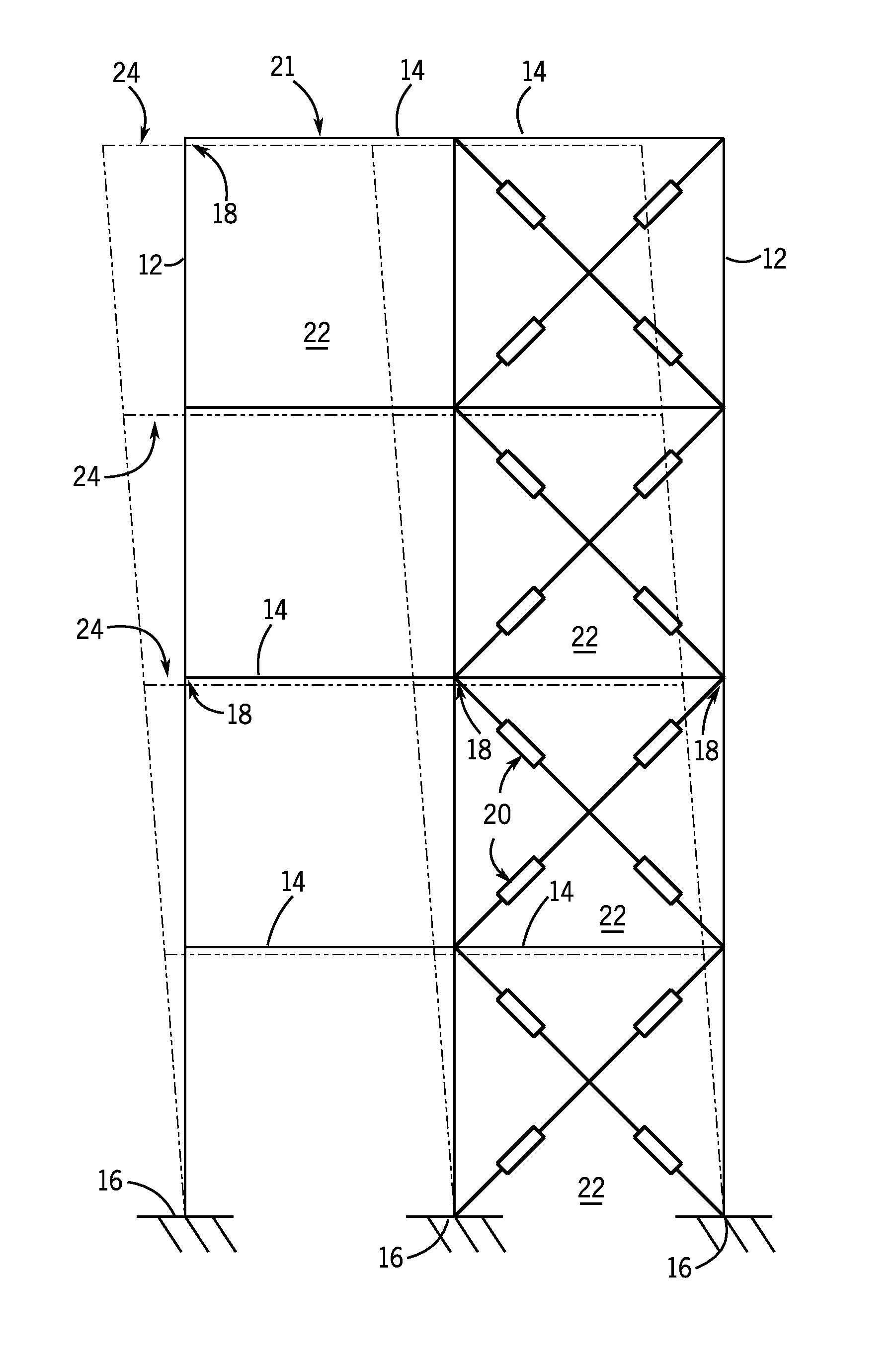
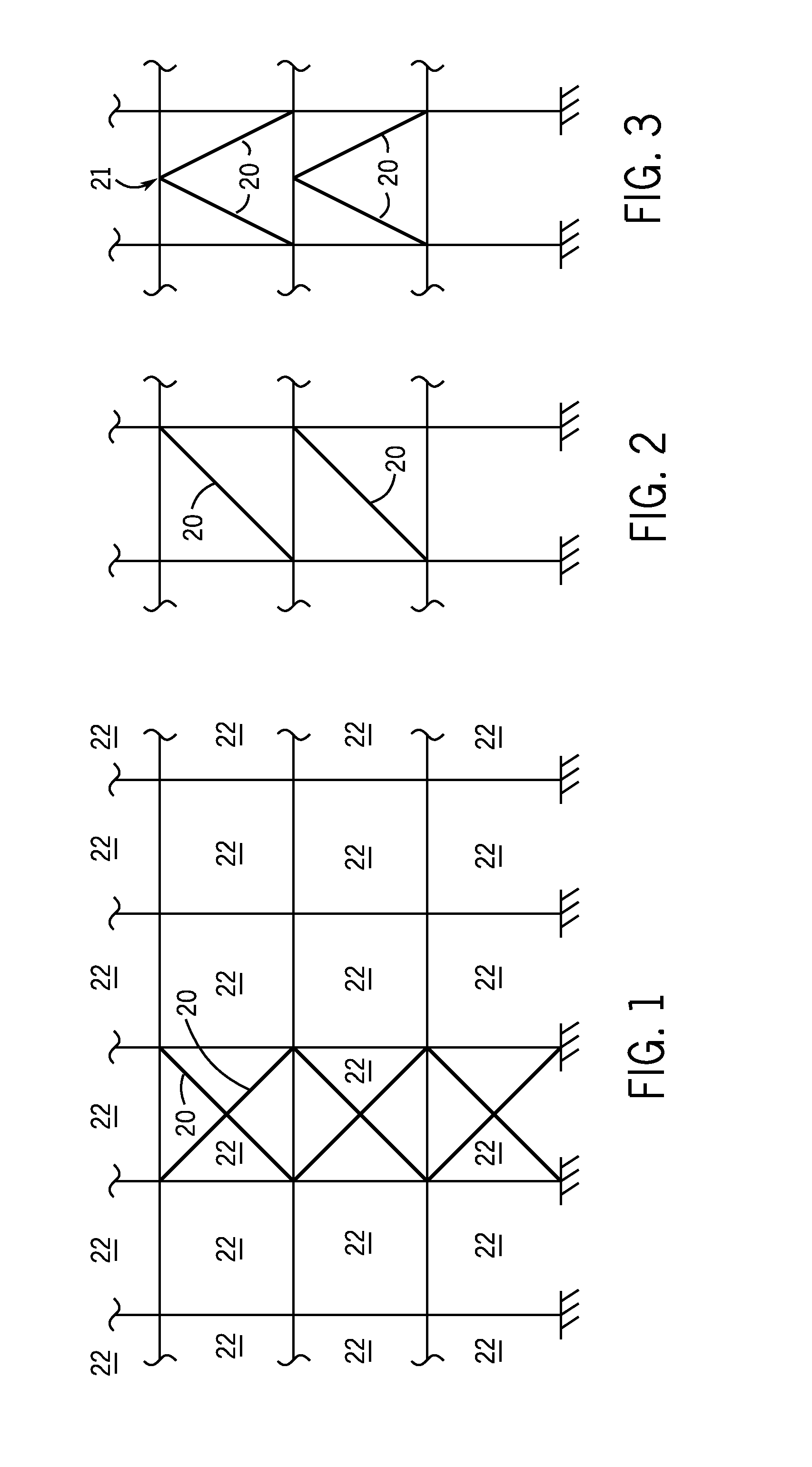
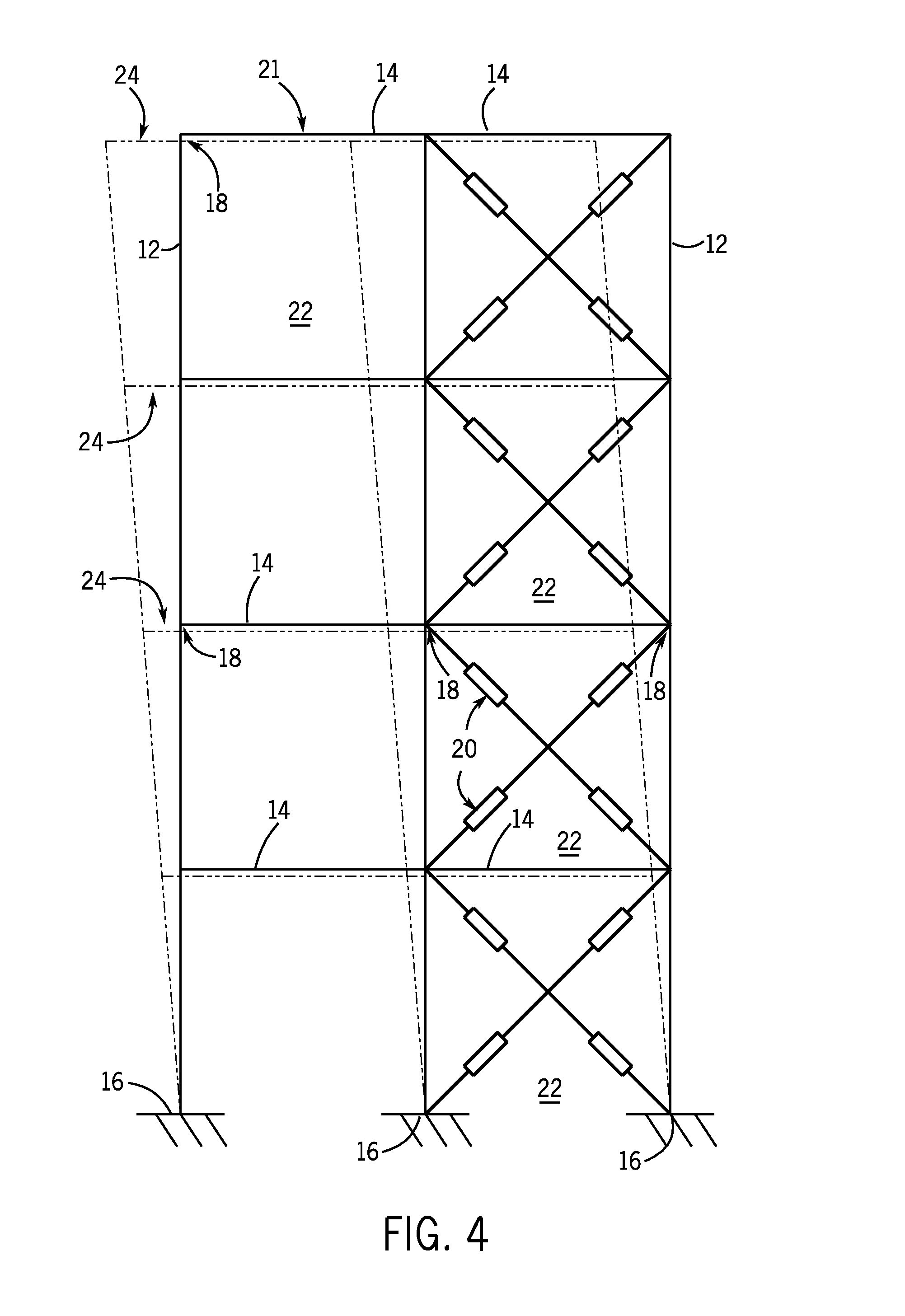
[0025]The operating environment of the invention is described with respect to a structural element, frame or framing system for a building or other structures subjected to transient loads, i.e., short term loading events including but not limited to seismic, wind, impact, machine, explosion, impulse, and moving loads. According to embodiments of the invention, such structural element, frame, or framing systems can occur and the invention can be implemented in architectural buildings, bridges, towers, mechanical process structures and other machine and mechanical designs to improve their response to various transient and non-transient loads; and otherwise protect structural frame components and systems from the adverse effects of overstress. Thus, embodiments of the invention are meant to encompass a variety of structural elements, structures and loading events applied thereto.

[0026]Referring to FIGS. 1-4, a structural frame 10 is schematically illustrated that incorporates embodimen...


PUM


Abstract

A structural frame for a building includes first structural members and second structural members, with a discontinuous elastic zone at locations where the first and second structural members are coupled and through which a load passes therebetween. Discontinuous elastic zone connections couple the first and second structural members and are configured to provide elasticity in the structural frame and dampen the effects of transient loads on the structural frame. Each discontinuous elastic zone connection includes faying surfaces opposing each other, fastening devices configured to secure respective first and second structural members, and a compression element positioned on each fastening device configured to act in combination with a fastening device to regulate movement of the faying surfaces relative to each other, and thus regulate the behavior of the discontinuous elastic zone connection resulting from loads applied by first and second structural members on opposing sides of a respective discontinuous elastic zone.

Description

BACKGROUND OF THE INVENTION[0001]Embodiments of the invention relate generally to structural framing systems and, more particularly, to structural connection mechanisms that are included in a structural framing system (primary, secondary, or other), to provide and allow for discontinuous elastic behavior of such system(s) for load conditions where plastic ductile behavior of commonly used beams and connection mechanisms would otherwise be relied upon. The discontinuous elastic behavior as described herein is achieved by constructing one or more of the structural framing system's connections, e.g., a beam to column connection, in a manner that comprises a zone in the load path of the connection where the stress strain behavior is more elastic than the elastic modulus of the base materials from which the connection is constructed of if constructed as a rigid connection, would predict.[0002]In areas prone to seismic loading events, structures such as buildings and bridges often include...

Claims


Application Information

Patent Timeline
Patent Type & Authority Applications(United States)
IPC IPC(8): E04B1/98
CPCE04B1/98F16B5/0266E04B2001/2415E04B2001/2442E04B2001/2448E04H9/024E04H9/0237E04H9/0215F16B7/00E04B1/19E04B1/1903
Inventor HAYES, TIMOTHY A.
Owner HAYES TIMOTHY A
Why Eureka
Try Eureka